Instruction Manual Model 1823A 2.
Introduction Thank you for purchasing our product. Electronic measuring instruments produced by us are high technology products made under strict quality control. We guarantee their exceptional precision and utmost reliability. For proper use of the product, please read this operation manual carefully. Note 1. To fully maintain the precision and reliability of the product use it within the range of standard setting (temperature 10 C~35 C, humidity 45%~85%) 2.
CONTENTS 1. PRODUCT DESCRIPTION 1-1. Introduction -----------------------------------------------------1-2. Technical Specifications -------------------------------------1-3. Equipment Ratings --------------------------------------------1-4. Supplied Accessories ------------------------------------------ (4) (5) (8) (8) 2. INSTALLATION 2-1. Initial Inspection ------------------------------------------------2-2. Connecting AC Power ----------------------------------------2-3.
1. PRODUCT DESCRIPTION 1-1. Introduction This reciprocal UNIVERSAL COUNTER series are microprocessor controlled instruments for frequency measurements at high resolutions within a short period of time. The 7 digit display with one second gate time is due to uniquely developed LSI as well as the expanding/reciprocal systems. It covers a frequency range from 0.1 Hz to 2.4 GHz based on 10 MHz time base T.C.
1-2. Technical Specifications INPUT A CHARACTERISTICS FREQUENCY RANGE : 0.1 Hz to 100 MHz (DC Coupled) 30 Hz to 100 MHz (AC Coupled) SENSITIVITY : 0.
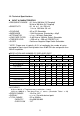
MAX INPUT VOLTAGE (ACV & DCV) MAX. INPUT VOLTAGE LEVEL 300 250 200 150 100 50 25 5 0 100 500 1K 1M 5M 10M 50M 100M FREQUENCY (Hz) FIG 1. MAX. Input Level. (Input A,B) INPUT B. CHARACTERISTICS = Same as Input A TIME INTERVAL(AB) RANGE LSD RESOLUTION ACCURACY MULTIPLIER : 0.1 uSec-10 Sec(0.1 Hz-10 MHz) : 100 nSec : ± LSD Trigger Error* : ± LSD Trigger Error Time base error x T.l : 1,10,100,1000 (Gate Time: 10 S,1 S,0.1 S,0.
INPUT C. CHARACTERISTICS FREQUENCY RANGE: 80 MHz to 2.4 GHz SENSITIVITY: 25 mV from 80 MHz to 150 MHz 20 mV from 150 MHz to 2.0 GHz COUPLING IMPEDANCE MAX. INPUT LEVEL 60 mV from 2.0 GHz to 2.4 GHz : AC only : 50 ±5% : 3 Vrms sine wave RESOLUTION AND NUMBER OF DISPLAYED DIGIT Time Base Selector INT EXT INT EXT INT EXT Gate Time 0.01 S 0.
displayed. When Hold is released, a new measurement begins. GATE TIME : Depending on input frequency < 10 mS------------Somewhere between 0.9 and 9 mS < 0.1 S--------------Somewhere between 9 and 90 mS < 1 S---------------- Somewhere between 90 and 900 mS < 10 S---------------Somewhere between 0.9 and 9 S NOTE: LAST MEASUREMENT DISPLAY WILL REMAIN FOR 10 SECONDS AFTER SIGNAL OFF. DIMENSION AND WEIGHT Dimensions WHD: 3.4 x 3.5 x 10.6 in (240 x 90 x 270 mm) Weight : Approx. 5.5 lb (2.5 kg.) 1-3.
Power cord-----------------------------------------------------------------1 Spare Fuse-----------------------------------------------------------------1 2. INSTALLATION 2-1. Initial Inspection This instrument was carefully inspected both mechanically and electrically before shipment. It should be physically free of damage. To confirm this, the instrument should be inspected for physical damage in transit. Also, check for supplied accessories. 2-2. Connecting AC Power 2-2.
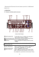
Allow more than 30 minutes for the unit to warm up so that it is stabilized and ready for use. 3. OPERATION 3-1.
the knob out and rotating it varies the level from negative to positive around the mid point. INPUT C, BNC : Input for frequency measurements above 80 MHz Female BNC connector terminated in 50 . LOW PASS FILTER : With this switch pushed in, the input B is routed through a SWITCH(LPF) low-pass filter with -3 dB point of approximately 100 kHz. When it is released, the input B signal is applied to the counter. Same as input B function for input A. ATT.
e. TOTAL A. When this mode is selected, the unit counts cycles of the input A signal and continuously displays that count. f. T.l (AB). When this mode is selected, the unit measures the time interval from an edge of the input A signal to an edge of the input B signal. Positive going or Negative going edge of each signal is selected By the slope switches. g. RATIO (A/B). When this mode is selected, the unit measures the ratio of input A frequency to the input B frequency.
VOLTAGE FUSE POWER MAX 0.5A F 15W 0.
RS-232C CONNECTOR : Connector for serial interfacing with a computer. 3-2. Operating Instruction Below is the basic operating information needed for frequency counter. a. Connect the unit to AC power cord into receptacle on rear panel and plug into AC inlet. b. To Turn on equipment, push power on-off switch on. c. set the function indicator position to FREQ A and Gate time indicator to 1 Sec position. CAUTION 1.
DC coupling position. 3-3-2 INPUT C (80 MHz to 2.4 GHz) CAUTION THE MAXIMUM INPUT LIMIT TO THIS INPUT IS 3 Vrms MAXIMUM OVER THE INPUT FREQUENCY RANGE. THE X 10 ATTENUATOR DOES NOT APPLY. a. Apply the signal to be measured to the input C. BNC. b. Set the function indicator to the FREQ. C position. c. Select the degree of resolution desired, using the gate time switch. d. Frequency is given by the display. The indicator lights while each measurement in progress. e.
3-6. Time Interval Measurements(AB) In time interval mode, unit measures the elapsed time from a selected edge of the input A waveform to a selected edge of the input B waveform. For a stable reading, the two input signals should be related to each other such that this time interval remains reasonably constant from one measurement to the next. For example, two digital waveforms derived from the same clock would be suitable; two arbitrary frequencies from separate function generators would not. a.
3-7. Frequency Ratio Measurements (A/B) In this mode of operation, the counter displays the ratio of the frequency applied to input A to the frequency applied to input B. The input A frequency should preferably be equal to or greater than that of input B. And both frequencies must be within the limits given in the "SPECIFICATIONS" section. Frequency ratio is determined by counting the number of input A cycles occurring during a specified number of input B cycles (1.10.100.
3-8. Use of RS-232C Serial Interfacing 1) Hardware/Software Requirements . IBM PC/XT/AT or compatible computer . Microsoft Windows . Serial port for connection with counter 2) Output Data Formats (1) Baud rate : 9600BPS 1 start bit (0) 8 data bit 1 stop bit (1) NONE PARITY (2) To Frequency counter Command Parameter 'H' : HOLD '0' : OFF '1' : ON '2' : TOGGLE 'G' : GATE '0' : 0.01 SEC '1' : 0.
4. MAINTENANCE CAUTION IT IS ESSENTIAL FOR SAFETY TO PROPERLY MAINTAIN AND SERVICE THIS INSTRUMENT WARNING VOLTAGES WITHIN THIS INSTRUMENT ARE SUFFICIENTLY HIGH TO ENDANGER LIFE. COVERS MUST NOT BE REMOVED EXCEPT BY PERSONS QUALIFIED AND AUTHORIZED TO DO SO AND THESE PERSONS SHOULD ALWAYS TAKE EXTREME CARE ONCE THE COVERS HAVE BEEN REMOVED. 4-1. Fuse Replacement Disconnect and remove all connections from any live power source. Unscrew fuse holder by screw driver.
5. OTHERS 5-1. BNC Cable Considerations Accuracy of radio frequency measurements can be affected by connections between signal source and counter. Main considerations are standing waves and shunt cable capacitance. Standing wave is usually present due to reflections when a transmission line is not terminated in its characteristic impedance.
5-3. Line Frequency Measurements Use of the attenuator, low pass filter, and/or x10 probe is advisable when measuring line frequency because the high amplitude signal and noise can cause wrong counting. WARNING USE CAUTION IN MEASURING THE LINE FREQUENCY OF AN AC OUTLET. USING THE PROBE TIP ONLY, MEASURE BOTH SIDES OF THE LINE. THE GROUND SIDE WILL GIVE A ZERO READING AND THE HOT SIDE WILL PROVIDE THE DESIRED MEASUREMENT. DO NOT USE THE "GROUND "LEAD OF THE PROBE.
Limited One-Year Warranty B&K Precision Corp. warrants to the original purchaser that its product and the component parts thereof, will be free from defects in workmanship and materials for a period of one year from the data of purchase. B&K Precision Corp. will, without charge, repair or replace, at its’ option, defective product or component parts. Returned product must be accompanied by proof of the purchase date in the form a sales receipt. To obtain warranty coverage in the U.S.A.
Model Number: ______________ Date Purchased:__________ Service Information Warranty Service: Please return the product in the original packaging with proof of purchase to the below address. Clearly state in writing the performance problem and return any leads, connectors and accessories that you are using with the device. Non-Warranty Service: Return the product in the original packaging to the below address.
22820 Savi Ranch Parkway Yorba Linda, CA 92887 USA TEL: 714-921-9095 FAX: 714-921-6422 www.bkprecision.com PN: 481-542-9-001 Printed in Korea 2004 B&K Precision Corp. V4.8.