BK PRECISION Instruction Manual Model 1795 High Current Power Supply
Limited Two Year Warranty B & K Precision Corp. warrants to the original purchaser that its product and the component parts therof, will be free from defects in workmanship and materials for a period of two years from the data of purchase. B & K Precision Corp. will, without charge, repair or replace, at its' option, defective product or component parts. Returned product must be accompanied by proof of the purchase date in the form a sales receipt. To obtain warranty coverage in the U.S.A.
TABLE OF CONTENTS SECTION PARTICULARS PAGE NO.
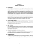
SECTION - 1 GENERAL INFORMATION 1.1 DESCRIPTION : The 1795 High Current Regulated D.C. Power Supply is completely solid and suitable for bench operation or standard 19" rack operation. It is a well regulated constant voltage / constant current supply which delivers 0-64V at 0-15Amps and can be adjusted continuously throughout the output range. When the supply is used as a constant voltage source the front panel VOLTAGE controls can be used to limit the output voltage.
SECTION - 2 SPECIFICATIONS OUTPUT VOLTAGE : LOAD CURRENT : CONSTANT VOLTAGE MODE REGULATION LINE : LOAD : RIPPLE & NOISE : CONSTANT CURRENT MODE REGULATION LINE : LOAD : RIPPLE & NOISE : OVERLOAD PROTECTION TRANSIENT RESPONSE : : Automatic overload and short circuit protection. 100µsecs to within 10mV of set output voltage for load change from 10% to 90%. : : ± 0.2% ± 10mV in constant voltage mode. ± 0.5% ± 10mA in constant current mode.
SECTION - 3 INSTALLATION 3.1 INITIAL INSPECTION : As soon as the power supply 1795 unit is unpacked, inspect for any damage that may have occurred during transit. Save all packing material until inspection is completed. If any damage is found, notify the carriers immediately. Our authorised representatives should also be notified. 3.
3.8 INPUT TAP SELECTION FOR 230V OPERATION : In case of 230V Mains operation please ensure that shorting links on the Tap Selector board is changed to 230V, marked on the PCB for both Mains Transformer & Auxilary Transformer. as per the following diagram. TAP SELECTOR BOARD Please make sure the input varistor is replaced by 20D 361K or equivalent for 230V Mains Operation at the Input of EMI Filter located at bottom side of the unit. 3.
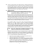
SECTION - 4 OPERATING INSTRUCTIONS 4.1 TURN ON SETTING PROCEDURE : The following procedure describes the use of controls and indicators for Constant Voltage and Constant Current Mode of Operation. CONSTANT VOLTAGE (CV) MODE : a. Set ‘POWER ON’ Switch & keep the OUTPUT ON/OFF switch to OFF position ( ). b. Press LIMIT switch and adjust the VOLTAGE controls till the desired voltage is indicated on Voltmeter ( ). c.
4.4 Positive or negative voltage can be obtained from this supply by grounding either one of the output terminals or one end of the load. Always use two leads to connect load to the supply, regardless of where the setup is grounded. This will eliminate any possibility of the output current return paths through the power source ground which would damage the line cord plug. This supply can also be operated upto ±300V DC above ground, if neither output terminal is grounded. 4.
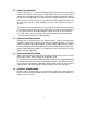
4.6 OUTPUT CAPACITANCE : Internal capacitor C3 ( L1791-FP-CNT-0603 PCB ) connected across the output terminals of the power supply, helps to supply high current pulses of short duration during constant voltage operation. Any capacitance added externally will improve the pulse current capability, but will decrease the safety provided by the constant current circuit.
OPERATORS SAFETY SUMMARY The general safety information in this part of the summary is for both operating & servicing personnel. Specific warnings and cautions will be found throughout the manual where they apply, but may not appear in this summary. TERMS IN THIS MANUAL : CAUTION : Statements identify conditions or practices that could result in damage to the equipment or other property. WARNING : Statements identify conditions or practices that could result in personal injury or loss of life.
USE THE PROPER FUSE : To avoid fire hazard, use only fuse of the correct type, voltage rating and current rating as specified in the parts list for your product. For 115V operation 20A, For 230V operation 10A Slow blow. Refer fuse replacement to qualified service personnel. DO NOT OPERATE IN EXPLOSIVE ATMOSPHERES : To avoid explosion, do not operate this instrument in an explosive atmosphere unless it has been specifically certified for such operation.
SECTION - 5 SERVICE INSTRUCTION 5.1 GENERAL : The instrument has been tested throughly and then released for dispatch.Normally, the unit works satisfactorily under all condition. However due to ageing / misuse or malfunctioning, the unit may become defective. In case, the user wants to carryout Servicing, the following instructions will be helpful in rectifying the defects. The Servicing shall be done only by Qualified personnel. 5.2 TROUBLE SHOOTING TECHNIQUES : 5.2.
checked by substituting a new component for it ( or one which has been checked previously). However, be sure that circuit conditions are not such that a replacement transistor might also be damaged. If substitute transistors are not available, use a dynamic tester. Static-type testers are not recommended, since they do not check operation under simulated operating conditions. An approved anti-static suction-type desoldering tool must be used to remove soldered-in transistors.
5.3.6 If Fuse blows, connect the unit through a variable AC Source with a current meter and monitor the current at no load. If the current is very high (more than 2 ampere or so ) load, check for Bridge Rectifier short or shorted Diode, or Secondary Winding short, etc 5.3.7 If output voltage or current DPM's are not reading, check for loose connections especially in crimping, soldering, of Connectors. WARNING THE FOLLOWING SERVICING INSTRUCTIONS ARE FOR USE BY QUALIFIED PERSONNEL ONLY.
5.4.3 VOLTAGES AT VARIOUS PINS OF IC LM324 IS AS FOLLOWS ( IC-101 ) :IC PIN NO. PIN1 -PIN1 -PIN2 & 3-PIN4 -PIN7 -PIN7 -PIN8 -PIN8 -PIN9 -PIN10 -PIN14 -CHECK CHECK CHECK CHECK VOLTAGES & CHECK CONDITIONS 0V ( WHEN V POT KEPT AT MIN. POSITION IN CV MODE ) +5V ( WHEN V POT KEPT AT MAX. POSITION IN CV MODE ) +4.9V AT V POT MAX. POSITION. +12V ALL CONDITION 0V AT CC POT MIN. POSITION. 0.5V AT CC POT MAX. POSITION. +1V TO 3.5V IN CV MODE. +10V TO +11V IN CC MODE. 0V. -6mV. +10 TO 11V IN CV MODE. 5.4.4 A. B.
your area. Before you purchase check the electrical parts list for the proper value rating, tolerance and description. 5.5.2 ORDERING PROCEDURE : When ordering replacement parts from B+K Inc. please include the following minimum information : 1. Power Supply Type ( 1795 B+K ). 2. Power Supply Serial Number ( For example, 03080001 ). 3. A description of the part ( if electrical include the circuit number ). 5.5.
CAUTION Static discharge can damage any semiconductor component in this instrument. This instrument contains electrical components that are susceptible to damage from static discharge. Static voltages of 1KV to 30KV are common in unprotected environments. Observe the following precautions to avoid damage : 1. Minimize handling of static-sensitive components. 2. Transport and store static-sensitive components or assemblies in their original containers, on a metal rail, or on conductive foam.
FAULT FINDING PROCEDURE ( A ) FUSE BLOWS FUSE BLOWS Is Line Voltage OK ? N Adjust Proper Line Voltage. N Insert proper rating Fuse. Y Is Fuse Rating OK ? Y Is Mains Transformer Tapping OK ? N Y Are Power Diodes Connected on Heat Sink Short ? Y Adjsut the Tap according to required voltage. Replace the Damaged Diodes. N Is Remote Sense Switch Pressed in Normal Condition ? N Y Release the Remote Switch in Normal Load Condition.
( B ) UNREGULATED O/P VOLTAGE UNREGULATED O/P VOLTAGE N Is IC LM324 OK ? Replace the IC. Y Is Voltage Pot Open OR Pot Wire is Reaching PCB ? N Replace the Voltage Pot and Ensure proper continuity with the PCB N Replace the Damaged Mosfet. Y Are Mosfets OK ? Y Is Gate Wire of Mosfet Reaching PCB ? N Ensure proper continuity of Gate Wire and PCB. Y Are Diodes D3 and D4 on Front Panel PCB OK ? N Replace the Damaged Diode.
( C ) NO OUTPUT VOLTAGE. NO O/P VOLTAGE N Replace It. Y Replace It. Is Voltage Selection Preset Open ? Y Replace It. Is IC LM324 OK ? Y Is Voltage Pot Short ? N N Are Zener Diodes Z1 & Z2, Preset VR1 on Preg. PCB OK ? N Replace It. Y Are all the Auxillary Winding Reaching PCB ? N Ensure their proper Connectivity with PCB. Y Is there proper contact of Load Terminal with Terminal Nuts Inside Unit. 1. Y Ensure proper Connectivity of Load Terminals and Terminal Nut inside.
( D ) NO DPM INDICATION. NO DPM INDICATION Is Display Completely Blank ? Y N Does Display shows only dot Indication ? Y Is Continuity between IC7805 & DPM OK ? N Ensure proper Continuity. Is Continuity between IC7905 & DPM's OK ? N Ensure proper Continuity. N Ensure proper Continuity. Y Is Continuity between ANGD & DPM's OK ? Y Is DPM IC OK ? N Replace It. 1. If there is no Indication at all ensure that there is proper Continuity between +5V Wire of DPM's and IC7805.
( E ) DPM NOT READ ( 000 ). DPM NOT READ ( V & I ) ( 000 ) Is DPM IC 707 OK ? N Replace It. N Ensure proper Continuity. N Replace It. Y Does Hi and Low Wire Reach DPM's ? Y IC TL431 OK ? Y Is minimum Resistance of Pot High ? Y Replace Pot. 1. Check whether Voltage Hi and Voltage Low Wire is reaching DPM. 2. Check DPM IC 7107. It might be Damaged. 3. Check minimum Output Voltage of Potemtiometer. It should be less than 150mV. 4. See that Power Supply is earthed properly. 5.
( F ) UNIT NOT TAKE CURRENT. UNIT NOT TAKE CURRENT Is Current Set Preset R21 OK ? N Replace It. Y Y Is Current Pot Short ? Replace It. N N Is Wiring Related to Current Pot OK ? Ensure proper Continuity. Y Are Load Terminals connected properly with Nut inside Unit ? N Ensure proper Terminal Contact. 1. Check Current set Preset R21. It might be open. 2. No Contact of Load Terminals with the Terminal Nut inside the Unit. 3. Current Pot might be Shorted. 6.
( G ) UNIT DIRECTLY GOES TO CC. UNIT DIRECTLY GOES TO CC Is Shunt Resistor open OR Dry Soldered ? Y Replace Shunt Resistor if necessary. N Is IC LM324 OK ? N Replace It. Y Replace It. Y Is Current select Preset R21 Open ? N Is Remote Sense Terminal Pressed ? Y Ensure Remote Sense Switch is Unpressed in Normal Condition. 1. Check the Shunt Resistor ( 0.025E / 25E ). It might be Open or Dry Soldered. 2. Check IC LM 324. It might be Damaged. 3. Current select Preset R21 might be Open. 6.
( H ) NO CURRENT CONTROL. NO CURRENT CONTROL Y Is Current Pot Open ? Replace it. N Are Wires related to Current Pot OK ? Y Ensure proper Connectivity. 1. Check the Current Potentiometer. It might be Open. 2. Check all Wires related to Current Potentiometer. (I) POOR LINE REGULATION. POOR LINE REGULATION Improper Device Drop Setting. N Leaky Summing Capacitor C4. Y Y Keep the Input Supply at rated I/P. Keep the O/P Supply at rated Vtg. and rated Load. Measure Vtg.
( J ) POOR LOAD REGULATION. POOR LOAD REGULATION Load Terminal Nut inside Unit might be Loose. N Is there any Oscillation in CV Mode ? Y N Reduce Resistor R6 ( 2.2K ) on F/Panel PCB until Oscillation dies OUT. If Oscillation still Prevail reduce R9 to 2K on F/Panel PCB. Is Capacitor C4 and C2 Leaky ? Y Replace It. 1. Load Terminal might be Loose. Ensure Terminals are tightened properly with Terminal Nuts inside the Unit. 2. There might be Oscillation at Output in CV Mode.
( L ) EXTERNAL PROGRAMMING NOT OK. EXTERNAL PROGRAMMING NOT OK Is Pot connected across INT & COM OK ? Y N Ensure 5K Pot connected between INT and COM Terminal. Is there proper Continuity between PROG Terminal and O/P +Ve ? N Ensure proper Connectivity. 1. Check whether 5K Pot is connected between INT and COM Terminal. 2. Check whether there is proper Continuity between PROG Terminal and Output Positive. (M ) REMOTE SENSE NOT OK. 1.
1. SECTION - 6 PART LIST & SCHEMATICS L1791-FP-CNT-0603 PCB ASSY Reference Designator RESISTORS R1 R2 R3 R4* R5 R6 R7* R8 R9 R10 R11 R12 R13 R14 R15 R16 R17 R18* R19 R20 R21 ZENERS Z1 DIODES D1 D2 D3 CAPACITORS C1 C2 C3 C4 IC U1 SWITCHES SW1-3 TERMINALS T1 T2 T3 T4 T5 Part Description Reference Designation Part Description 1K Not Used 100E 3K 1K 1K1 4K7 6K8 6K8 15K 1K 1K 1K, 10W 1K 1K 3.
1. L1791-FP-CNT-0603 PCB ASSY Reference Designator CONNECTORS J1 J1 CLAMPS SW1 SW2 SW3 SWITCHES SW1 SW2 SW3 2. Part Description Reference Designation Part Description J2.54 - 3MSL, 3 PIN SIL 2.54mm ST LOCK MALE J2.54 - 3FSL, 3 PIN SIL 2.54mm ST LOCK FEMALE SINGLE PUSH SWITCH MTG. CLAMP DOUBLE PUSH SWITCH MTG. CLAMP DOUBLE PUSH SWITCH MTG.
2. PS-PREG-1791-0503 PCB ASSLY Reference Designator Part Description TRANSISTORS Q1 Q2 Q3 ZENERS Z1 PRESET VR1 TRANSFORMER T1 3. Reference Designation BC 109 MPSA12 BC 557 Q4 Q5 BC 557 BC 547 4.7V, ½W Z2 10V, ½W Part Description 5K ( 3206F ) HOR EE25 PULSE TX. Z-DPM/01 REV - 01 X 2 Reference Designator Part Description Reference Designation RESISTORS R1 39K, 0.25W, 5%, MFR R6 R2 470K, 0.25W, 5%, MFR R7 R3 1M, 0.25W, 5%, MFR R8 R4 SEL ( INPUT ) R9 R5 10K, 0.
4. PS-AUX-DC-L1791-0503 PCB ASSLY Reference Designator CAPACITORS C1 C2 C3 C4 C5 C6 C7 ICs U1 U2 BRIDGE BR1 DIODES D1 D2 D3 CONNECTORS J1 J1 J2 J2 5.
6. FRONT PANEL ASSLY Reference Designator Part Description Reference Designation Part Description POT VR1 VR2 5K, WWPOT 1K, WWPOT VR3 VR4 500E, WWPOT 50E, WWPOT SWITCH SW1 20A/250V ON/OFF SWITCH 7. MAIN CHASSIS ASSLY Reference Designator Part Description RESISTOR R1 R2 4.7K/2W, MOR 0.
31 1. 2. 3. 4. 5. Power ON / OFF Switch. Voltage Coarse Control. Voltage Fine Control. Voltage DPM. Current Coarse Control. 6. 7. 8. 9. 10. Current Fine Control. CV Mode INdication. Current DPM. CC Mode Indication. Output Preset Switch. 11. 12. 13. 14. 15. FRONT PANEL LAYOUT Output ON / OFF Switch. Output Terminals. Remote Sense Switch. Remote Sense Terminal.
32 1. 2. INPUT FUSE HOLDER MAINS CORD. 3. 4. INT / EXT PROGRAM TERMINAL PROTECTIVE GROUND BACK PANEL LAYOUT 5. 6. COOLING FAN. VENTILATION.
33 TOP VIEW
BOTTOM VIEW OF MODEL : 1790 / 1791 34
FRONT PANEL CONTROL PCB OF 1790 / 1791 35
POWER MODULE PCB OF 1790 / 1791 36
PRE REGULATOR / AUX.
Service Information Warranty Service : Please return the product in the original packaging with proof of purchase to the below address. Clearly state in writing the performance problem and return any leads, connectors and accessories that you are using with the device. Non-Warranty Service : Please return the product in the priginal packaging to the below address. Clearly state in writing the performance problem and return any leads, connectors and accessories that you are using with the device.
BK PRECISION B & K PRECISION CORP. SN: 480-808-9-001 Printed in India (M-00285) 22820 Savi Ranch Parkway Yorba Linda, CA 92887 www.bkprecision.