
User guide

22
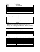
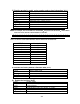
Status packets
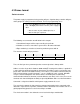
When you send a command that does not cause the power supply to send requested
information back to you, you will receive a status packet back. The structure of a status
packet is
Byte 0
Byte 1
Byte 2
Byte 3
Byte 4 to 24
Byte 25
0xAA
Address
0x12
Status byte
Reserved
Checksum
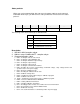
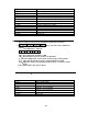
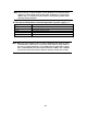
The meaning of the return status byte is defined below:
0x90
Checksum incorrect
0xA0
Parameter incorrect
0xB0
Unrecognized command
0xC0
Invalid command
0x80
Command was successful
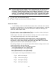
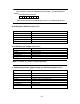
Description:
1. Start bit is 0xAA, occupies a byte.
2. Address range is 0x00 to 0xFE,occupies a byte.
3. Command occupies a byte.
a. 0x20----Setting the remote control mode
b. 0x21----Setting the output ON/OFF state
c. 0x22----Setting the maximum output voltage
d. 0x23----Setting the output voltage
e. 0x24----Setting the output current
f. 0x25----Setting the communication address
g. 0x26----Reading the present current/voltage, maximum voltage, setup voltage/current and
operation states of the power supply.
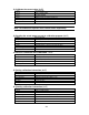
h. 0x27----Enter the calibration mode
i. 0x28----Reading the calibration mode state
j. 0x29----Calibrate voltage value.
k. 0x2A----Sending the actual output voltage to calibration program.
l. 0x2B----Calibrate current value.
m. 0x2C----Sending the actual output current to calibration program
.
n. 0x2D----Save the calibration data to EEPROM.
o. 0x2E----Setting calibration information.
p. 0x2F----Reading calibration information.
q. 0x31----Reading product’s model, series number and version information.
r. 0x32----Restoring the factory default calibration data.
s. 0x37----Enable the local key.
t. 0x12----The return information of command operation in power supply.