Instruction Manual 1 Programmable DC Power Supplies Model 1785B, 1786B, 1787B & 1788
Content Content ..................................................................................................................................................... 2 Quick Reference ............................................................................................................................................. 3 About your safety.................................................................................................................................... 3 General information.............
Quick Reference About your safety Pease review the following safety precautions before operating our equipment. General information The following safety precautions should be observed before using this product and any associated instrumentations. Although some instruments and accessories would be used with non-hazardous voltages, there are situations where hazardous conditions may be present.
Certification and Warranty Certification We certify that this product met its published specifications at time of shipment from the factory. Introduction The 1785B - 1788 Series power supplies are high performance single-output programmable DC power supplies with communication interface. The combination of bench-top and system features in these power supplies provides versatile solutions for your design and test requirements.
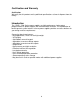
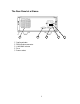
The Front Panel at a Glance ① ② ③ ④ ⑤ ⑥ ⑦ 10 digits VFD display Status information for operating mode and working status Power switch Number keys Function keys UP/DOWN and ENTER key Output terminals Function keys description V-set I-set Save Recall Menu Out on/off Set the output voltage value Set the current value Save the present settings to a specified register location(1~16) Recall a saved settings from location ‘‘1’’through ‘‘16’ Menu function to set related parameters of the power supply Output O
Menu description Menu >MAX VOLT >INIT OUT >INIT VOL >KEY SOUN >BAUD RATE >ADDR >KEY LOCK >EXIT Set the maximum output voltage value Initiate the output state to ON or not Initiate the output voltage to 0 volt or not Switch On/Off the buzzer sound when you press any key Set the communication baud rate Set the communication address Set the password for function keys Exit Display annunciators OFF * The power supply’s Timer output is off Constant voltage Sense mode Constant current Ext mode Adrs Not used
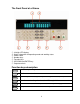
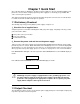
The Rear Panel at a Glance 1 ① ② ③ ④ ⑤ 2 3 Cooling window DB9 interface connector 110V/220V selector Fuse Power socket 7 4 5
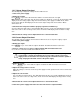
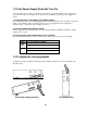
Chapter 1 Quick Start One of the first things you will want to do with your power supply is to become acquainted with the front panel. The exercises in this chapter prepare the power supply for use and help you get familiar with some of its front-panel operations. This chapter is intended for both the experienced and the inexperienced user because it calls attention to certain checks that should be made prior to operation. 1.
1.2.1 Voltage Output Checkout The following steps verify basic voltage functions without load. 1. Turn on the power supply. 2. Enable the outputs. Press Out on/off key to let the ON annunciator and the CV annunciator turn on to light. Notice: if the voltage value flash, then the power supply is in Set mode, ‘‘Set mode’’ means that the VFD display shows the setting output voltage and current.
1.3 If the Power Supply Does Not Turn On Use the following steps to help solve problems you might encounter when turning on the instrument. If you need more help, refer to chapter 6 for instructions on returning the instrument to the supplier for service. 1. Verify that there is AC power to the power supply. First, verify that the power cord is firmly plugged into the power receptacle on the rear panel of the power supply.
1.5 To Rack Mount the Instrument You can mount the power supply in a standard 19-inch rack cabinet using the IT-E151 rack mount kit. Note: Remove the carrying handle and the two plastic ears before rack-mounting the instrument. To remove the handle, grasp the handle by sides and pull outwards and rotate it to a special position to let the arrow on the handle and the arrow on the plastic ears be in opposite directions, then pull the handle outward.
unit (mm) Dimension 12
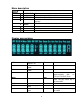
Chapter 2 Specifications 2.1 Specifications Parameter Voltage Output Ratings, ( 0 °C - 40 °C) Current LVP 1785B 0 ~18 V 1786B 0 ~32 V 1787B 0 ~72 V 0~1.5 0 ~5 A 0 ~3 A A 0 ~19 0 ~33 0 ~73 V V V (rated current < 3 A) <0.01% (rated current< 10 A) <0.02% Load Regulation, ±(%of output+offset) Voltage Current <0.1% + 5 mA Line Regulation, ±(%of output+offset) Voltage <0.1% + 3 mV Current <0.
2.2 Supplemental Characteristics State Storage Memory Sixteen (16) user-configurable stored states Recommended Calibration Interval 1 year AC Input Ratings (selectable via switch on the rear panel) Option OP1: 220VAC ± 10%, 47 to 63 Hz Option OP2: 110 VAC ± 10%, 47 to 63 Hz Maximum input power 350VA Cooling Fan cooled Operating Temperature 32 to 104 °F (0 to 40 °C) for full rated output Storage Temperature -68 to 158 °F (-20 to 70 °C) for storage environment.
(Unit: mm) 15
Chapter 3 Front-panel Operation So far you have learned how to install your power supply and do quick start. During the quick start, you were briefly introduced to operating from the front panel as you learned how to check basic voltage and current functions. This chapter describes in detail the use of the front-panel keys and shows how they are used to accomplish power supply operation.
Step1. Power on the Power Supply Step2. Press the ▲ and ▼ keys to change the value Solution 2: Step1. Power on the instrument Step2. Press V-Set key. 0 Step3. Use the numeric keys Step4. Press Enter 9 to or ▲ and ▼ keys to change the voltage value. to confirm the value 3.3 Constant Current Operation The constant current output range is from 0A to the maximum current value of each type. It is very easy for you to set the constant current output. Step1. Power on the Power Supply Step2.
supply. Step1. Press Menu key. Step2. Select >MAX VOLT by using▲ and ▼ key. Step3. Press Enter key. Step4. Change the voltage value by using numeric keys Step5. Press Enter 0 to 9 or ▲and ▼key. key. Note: After you setting the maximum voltage value, the output voltage setup should be in the range from 0 volt to maximum voltage. The default maximum voltage is the full voltage range of its model.
Note: Default baud rate is 4800. Setting Address (>ADDRESS) This instruction can set the communication address for each power supply. The address range is from 0 to 30. Before the communication, you must make sure that there is same address between the power supply and the computer. Note: Default address is 0. When the power supply receives a frame instruction from computer, the LINK indicator will light on; it means that the power supply started to communicate with computer.
Chapter 4 Remote Operation Mode The DB9 interface connector on the rear panel of the power supply can be transferred to RS-232 interface, the following information will tell you how to use the computer to control the output of the power supply. 4.
4.3 Frame format Packet structure The power supply is programmed using packets of bytes. A packet always contains 26 bytes, either going to or coming from the instrument. The basic programming rule is: You send a 26 byte packet to the instrument. You then read a 26 byte packet back from the power supply to either • Get the status of your submitted packet, or • Get the data you requested. The following are conventions we will follow in this chapter: 1.
Status packets When you send a command that does not cause the power supply to send requested information back to you, you will receive a status packet back.
Note: You must change the power supply to remote control mode first, then you can control the power supply output by computer. The command for remote control is 0x20. If you want to calibrate the power supply, set the calibration information. If you want to set the product serial number, you must set the calibration protection mode to OFF state first. The command for calibration protection is 0x27. When the power supply is in calibration mode, changes for the output state of power supply are not allowed.
4.4 Communication protocol 1.Setting the remote control mode (0x20) st Start bit( 0xAA ) nd Address(0x00~0xFE) rd Command (0x20) Operation mode(0 represent front panel operation mode, 1 represent remote operation mode) System reserve Check sum 1 byte 2 byte 3 byte th 4 byte th th 5 to 25 byte th 26 byte Note: You cannot control the power supply from the front panel when the power supply is in calibration mode.
4.
th 9 byte Byte 3 of measured output voltage th Power supply’s state th Byte 0 of current value setting (current limit value) th Byte 1 of current value setting Byte 0 of the maximum voltage setting Byte 1 of the maximum voltage setting Byte 2 of the maximum voltage setting Byte 3 of the maximum voltage setting Byte 0 of voltage value setting Byte 1 of voltage value setting Byte 2 of voltage value setting Byte 3 of voltage value setting System reserve Check sum 10 byte 11 byte 12 byte th 13 byte th
Note: We use a byte to represent calibration protection state,each bit is defined as follows: from higher bit to lower bit 7 6 5 4 3 2 1 0 0 bit:Protection state, 0 is to disable protection, 1 is to enable the protection. 9. Reading the calibration state (0x28) st Start bit(0xAA) nd Address(0x00~0xFE) rd Command(0x28) Calibration protection state System reserve Check sum 1 byte 2 byte 3 byte th 4 byte th 5 byte th 26 byte 10.
12. Calibrate the current value (0x2B) st Start bit(0xAA) nd Address(0x00-0xFE) Command(0x2B) th Calibrated current points( point 1-2) System reserve Check sum 1 byte 2 byte rd 3 byte 4 byte th th 5 to 25 byte th 26 byte Note: To calibrate the 2 points of the current value sequentially. 13.
17. Reading product’s model, series number and version information (0x31) st Start bit (0xAA) nd Address (0x00~0xFE) Command (0x31) Product model(ASIC code) Lower byte of the software version Higher byte of the software version Serial number(ASCII code) System reserve 1 byte 2 byte rd 3 byte th th 4 to 8 byte th 9 byte th 10 byte th th 11 to 20 byte st th 21 to 25 byte th 26 byte Check sum Note: For example, the serial number is 0123456789,the product model is 6811,and software version is V2.
Note: The local keys on the front panel are not allowed to use when the power supply is in remote mode. If the local key was enabled, user can press the numeric key 7 to change the remote mode to front panel operation mode and all local keys will work. 20.
Chapter 5 PV1785B-1788 Software 5.1 Introduction Software PV1785B-1788 is control software for IT1785B-1788 series programmable power supply. It can work with all single-output power supply models. Please make sure that you purchased communication cable, and use it to connect the power supply and computer before the communicating. This software can accomplish all the functions of the power supply, such as setting constant voltage, setting constant current, max voltage etc.
1 Configure the software operation environments. 2 Voltage chart, it can show you a chart of the voltage. 3 Current chart: it can show you a chart of the current. 4 5 To set the remote mode of power supply. 6 To enable the local numeric key ⑦,it means that if you select “Enable” on this button, when the power supply is under remote control mode, you can press numeric key ⑦ to change the control mode to front panel control mode. To set the output state ON/OFF 7 Annunciators display.
5.3.2 Status bar Status bar will give you the communication information. When the communication is successful, the status bar will display as follows: Model number Communication status 1. Model number: it will display the real part number of the field power supply which detected by the computer. (6811/6812/6821/6822/6823……..). 2.
2. Quickly setting Hot Key: Right-click each Hotkey Button, it will display as “Modify Voltage/Current”. Click “Modify/Voltage/ Current”, it will display as follows, change the voltage/current value as you desired, then click OK button to confirm. Voltage Sweep: To set voltage sweep. For example, StartValue=1V, Stop Value=12V, Voltage Step=0.5V, TimeDelay=2s.
5.3.4. GO/NG Test Function GO/NG is an auto test function, to test if the EUT (equipment under test) can meet the specification. To use this function, follow up the steps below: 1. Right-click on the window, the edit tools (Append a line, Insert a line, Delete a line, Delete Select etc.) will appear on the window. Use the edit tools to edit the test steps. 2. To set the Voltage, Max Amps, Min Amps and Delay time according to the specifications of the EUT. 3. Click the Run button to start the test.
5.3.7 Chart Description The voltage and current chart can help you to analyze voltage and current changes more easily. We take the voltage chart as the example to let you know how to use it. The chart window is as follows: Click here and move to zoom in/out axes or scroll axes To set the Y-Axes Span To set the X-Axes Span Vertical marker Horizontal marker XY Value marker Limit range between the minimum value and maximum value. Scroll axes mode Zoom in/out axes mode Zoom out Zoom in Save the chart as a .
SERVICE INFORMATION Warranty Service: Please go the support and service section on our website www.bkprecision.com to obtain a RMA #. Return the product in the original packaging with proof of purchase to the address below. Clearly state on the RMA the performance problem and return any leads, probes, connectors and accessories that you are using with the device. Non-Warranty Service: Please go the support and service section on our website www.bkprecision.com to obtain a RMA #.
22820 Savi Ranch Parkway Yorba Linda, CA 92887 www.bkprecision.com © 2008-2012 B&K Precision Corp.