INSTRUCTION MANUAL MODELS: 1760A, 1761, 1762 Triple Output DC POWER SUPPLY With Dual 4-Digit LED Displays
TEST INSTRUMENT SAFETY WARNING Normal use of test equipment exposes you to a certain amount of danger from electrical shock because testing must sometimes be performed where exposed high voltage is present. An electrical shock causing 10 milliamps of current to pass through the heart will stop most human heartbeats. Voltage as low as 35 volts DC or AC rms should be considered dangerous and hazardous since it can produce a lethal current under certain conditions. Higher voltages are even more dangerous.
Instruction Manual For Models 1760A, 1761, 1762 Triple Output DC Power Supplies With Dual 4-Digit LED Displays 22820 Savi Ranch Parkway Yorba Linda, CA 92887 www.bkprecision.
TABLE OF CONTENTS page TEST INSTRUMENT SAFETY ------------- inside front cover Page APPLICATION ---------------------------------------------------- 33 General -------------------------------------------------------------- 33 Electronics Servicing ---------------------------------------------- 33 Electronics Manufacturing ---------------------------------------- 33 Electronics Design Lab -------------------------------------------- 34 Electronics Education --------------------------------------------- 34 B
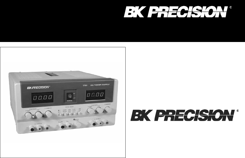
INTRODUCTION These B+K Precision Triple Output DC Power Supplies are high quality, general purpose DC power sources. They provide two “main” supplies and a “third” auxiliary output with a 4-6.5V (2-6.5V for models 1761 & 1762) DC output. The “main” V supplies are adjustable with both coarse and fine voltage controls for precise settability and are capable of current output of 0-2A (0-3A for model 1761).
The features and versatility of the unit, especially the triple output and tracking features, make it an ideal general purpose power supply for engineering lab applications. It can serve as a single or multi-voltage power source, including the bias supply, for breadboard and prototype circuits and equipment. It can provide single or simultaneously varying voltages for circuit evaluation. It can provide tracking (+) and (-) voltages for evaluating differential amplifiers.
FEATURES TRIPLE OUTPUT Operates as three separate power supplies. Each has floating output and is completely isolated from the other two. CONSTANT VOLTAGE OR CONSTANT CURRENT The “A” and “B” supplies provide regulated DC voltage output or regulated DC current output. Crossover is smooth and automatic. ONE 4-6.5 V (1760A) or 2-6.5 V (1761 & 1762) SUPPLY Durable 0-to-5 amp supply is ideal for use with most digital logic circuitry. Adequate current capacity for extensive circuitry.
SPECIFICATIONS “A” AND “B” SUPPLIES Output Voltage Range: 0V to 30V (model 1760A) 0V to 35V (model 1761) 0V to 60V (model 1762) Output Current Limit Range: 0.1A to 2A (model 1760A and 1762) 0.1A to 3A (model 1761) Load Regulation (Constant Voltage): ≤0.01% + 3 mV Line Regulation 108 - 132 V (Constant Voltage): ≤0.01% + 3 mV Ripple (Constant Voltage): ≤1 mV RMS Recovery Time (Constant Voltage): ≤100 uS Temp. Coefficient (Constant Voltage): <300 ppm/°C Load Regulation (Constant Current): ≤0.
SPECIFICATIONS GENERAL Power Requirements: Domestic: 120 VAC + 10%, 60 Hz International: 120/220/230/240 VAC -* 10%, 50/60 Hz Power Consumption (Fully Loaded): Approximately 350 W Protection: Reverse polarity protection and current limiting. Dimensions (H x W x D): 5.7" x 10.5" x 15" (145 mm x 267 mm x 381 mm) Weight: 10 kg (21 lbs) Accessories Supplied: Two earth ground bus straps. NOTE: Specifications and information are subject to change without notice. Please visit www.bkprecision.
CONTROLS AND INDICATORS GENERAL CONTROLS AND INDICATORS 1. 0-30V/4-6.5V Switch. Controls “A”/4-6.5V LED Display. When this switch is in the 0-30V position (out), the LED display monitors the “A” (0-30 V) supply. When this switch is in the 4-6.5V position (in), the LED display monitors the 4-6.5V supply. 2. Right V/A Switch. Selects current or voltage metering mode for the “A” 0-30 V supply or the 4-6.5 V supply (depending on setting of 0-30 V/4-6.5 V switch).
CONTROLS AND INDICATORS Fig. 1. Front Panel Controls and Indicators.
CONTROLS AND INDICATORS “A” SUPPLY CONTROLS AND INDICATORS 16. C.C. (Constant Current) Indicator. Red LED lights when “A” supply is in the Constant Current mode. The Power Supply regulates the output current at the value set by the “A” CURRENT control. In the Parallel Tracking mode, when this indicator is lit, both the “A” and “B” supplies are in the Constant Current mode. 17. C.V. (Constant Voltage) Indicator. Green LED lights when the “A” supply is in the Constant Voltage mode.
CONTROLS AND INDICATORS 25. Coarse VOLTAGE Control. Coarse adjustment of the output voltage of the “B” supply when the INDEPendent mode is selected. Also sets the 5% to 100% tracking in the SERies TRACKing mode. Disabled in the PARallel TRACKing mode. Read the value on the “B” LED Display when the voltage (V) metering mode is selected. 26. Fine VOLTAGE Control. Fine adjustment of output voltage of the “B” supply when the INDEPendent mode is selected.
OPERATING INSTRUCTIONS SAFETY PRECAUTIONS CAUTION Avoid contacting the heat sink at the rear of the power supply. When the unit is providing large amounts of current at any or all of its outputs, the heat sink can become very hot. Contacting the heat sink when it is hot could result in skin burns or damage to the equipment in contact with them. Use only a polarized 3-wire AC outlet.
OPERATING INSTRUCTIONS Hook-up 1. Disengage the INDEP/TRACK mode switch so that the power supply is in the INDEPendent operating mode. 2. Turn off the power supply and the equipment to be powered during hook-up. 3. Connect the positive polarity of the device being powered to the red (+) terminal of the power supply. 4. Connect the negative polarity of the device being powered to the black (-) terminal of the power supply. 5. Fig. 3 illustrates the grounding possibilities when used in the INDEPendent mode.
OPERATING INSTRUCTIONS Fig. 3. Independent Operation Grounding Possibilities.
OPERATING INSTRUCTIONS Fig. 3. Independent Operation Grounding Possibilities.
OPERATING INSTRUCTIONS Typical Constant Voltage Operation 1. Before connecting the device to be powered to the power supply, determine the maximum safe load current for the device to be powered and set the current limit value (see “Setting Current Limit” procedure in this section). 2. Set Fine VOLTAGE control to center and Coarse VOLTAGE control to minimum (fully counterclockwise). 3. Turn off power supply and connect it to the device to be powered (see “Hook-Up” procedure in this section). 4.
OPERATING INSTRUCTIONS Setting Current Limit 1. Determine the maximum safe current for the device to be powered. 2. Temporarily short the (+) and (-) terminals of the power supply together with a test lead. 3. Rotate the Coarse VOLTAGE control away from zero sufficiently for the CC indicator to light. 4. Set the meter selection switch to the A position to select the current metering mode. 5. Adjust the CURRENT control for the desired current limit. Read the current value on the LED display. 6.
OPERATING INSTRUCTIONS Typical Constant Current Operation 1. Before connecting the device to be powered to the power supply, determine the maximum safe voltage to be applied, set the meter selection switch to the V position, and set the VOLTAGE controls to obtain that voltage reading on the LED display. 2. Determine the desired constant current value. 3. Set the CURRENT control to minimum (fully counterclockwise). 4. Turn off the power supply and connect it to the device to be powered. 5.
OPERATING INSTRUCTIONS Constant Voltage/Constant Current Characteristic The working characteristic of this power supply is called a constant voltage/constant current automatic crossover type. This permits continuous transition from constant current to constant voltage modes in response to the load change. The intersection of constant voltage and constant current modes is called the crossover point. Fig. 7 shows the relationship between this crossover point and the load.
OPERATING INSTRUCTIONS SERIES TRACKING OPERATION When the series tracking mode of operation is selected, the positive (red) terminal of the “B” supply output is internally connected to the negative (black) terminal of the “A” supply. This allows the power supply to be used as a single 0-to-60 volt power supply simply by using the negative (black) terminal of the “B” supply and the positive (red) terminal of the “A” supply.
OPERATING INSTRUCTIONS Fig. 8.
OPERATING INSTRUCTIONS Fig. 8.
OPERATING INSTRUCTIONS a. Similarly, the positive polarity can be grounded by strapping the red (+) terminal of the “A” supply to the green terminal of the “A” supply as shown in Fig. 8B. b. If “split supply” operation is desired, a positive and negative voltage with a center ground can be achieved by strapping the black (-) terminal of the “A” supply to the green ( ) of the “A” supply as shown in Fig. 8C. See the APPLICATIONS section of this manual for more information on “split supply” operation.
OPERATING INSTRUCTIONS 9. Observe proper polarity. If the circuit being powered is not equipped with reverse polarity protection, damage to the circuit can result from reverse polarity. Use color coded hook-up leads, for convenience in identifying polarity, red for (+) and black for (-). 10. Make sure that the hook-up leads offer sufficient current capability and low resistance between the power supply and the circuits being powered.
OPERATING INSTRUCTIONS Fig. 9.
OPERATING INSTRUCTIONS Fig. 9.
OPERATING INSTRUCTIONS 9. Observe proper polarity. If the circuit being powered is not equipped with reverse polarity protection, damage to the circuit can result from reverse polarity. Use color coded hook-up leads, for convenience in identifying polarity, red for (+) and black for (-). 10. Make sure that the hook-up leads offer sufficient current capability and low resistance between the power supply and the circuits being powered. 10-amp test leads are available as an optional accessory. 4-6.
OPERATING INSTRUCTIONS Fig. 10. Grounding Possibilities for 4-6.
OPERATING INSTRUCTIONS Fig. 10. Grounding Possibilities for 4-6.
OPERATING INSTRUCTIONS 10. If the red OVERload indicator lights, too much load has been placed on the supply. This will cause voltage and current to drop and prevent proper operation of the 4-6.5V supply. To correct this situation, the load on the supply must be decreased so that no more than 5 amps of current are required. 32 NOTE If decreasing the load does not cause the overload indicator to turn off, the overvoltage protection circuitry has activated.
APPLICATIONS GENERAL The Model 1760A/1761/1762 power supply has a very wide variety of applications in electrical and electronics servicing, engineering laboratories, manufacturing and testing facilities, schools, and home hobbying. The “A” and “B” power supply outputs are fully adjustable from 0-30V (1760A), 0-35V (1761), or 0-60V (1762) and 0-2A (1760A and 1762) or 0-3A (1761) and the 4-6.5V (1760A) or 2-6.5V (1761 & 1762) supply is fully adjustable with a current capability of 0-5A.
APPLICATIONS ELECTRONICS DESIGN LAB The technician or engineer working in an engineering laboratory requires a DC power supply to power breadboard and prototype circuits. This power supply is ideal because it monitors output current and voltage, limits current to protect the circuit, is adjustable over a wide range, and has excellent regulation and very low ripple.
APPLICATIONS Two Identical Positive Voltages Negative (Refer To Fig. 11) With a Common Some electronic equipment requires two identical positive voltages with a common negative. A good example of this would be a digital car clock where there are two +12 volt inputs and a common negative. Using both supplies in the parallel tracking mode would provide the simplest hook-up and operation. This type of “split supply” operation is obtained as follows: 1.
APPLICATIONS Two Differing Positive Voltages With a Common Negative (Refer To Fig. 12) Many electronic circuits require two different positive voltages with a common negative. A typical example of this would be a device that uses both TTL (+5 V) and analog (typically +15 V) circuitry. Using both supplies, two differing positive voltages with a common negative are obtained as follows: 1. Select the INDEPendent operating mode and set up the LED displays so that both displays monitor voltage. 2.
APPLICATIONS Two Identical Negative Voltages With a Common Positive (Refer To Fig. 13) When the same negative voltage is required at two points in the same circuit and a common positive is needed, perform the following: 1. Connect the ground strap between the positive terminal and the ground of the “A” supply. 2. Set the desired voltage and maximum current using the “A” VOLTAGE and CURRENT controls. 3. Turn off the power supply and the equipment to be powered during hook-up. 4.
APPLICATIONS Two Differing Negative Voltages With a Positive Common (Refer To Fig. 14) Using both supplies, two differing negative voltages with a common positive are obtained as follows: 1. Select the INDEPendent operating mode and set up the LED displays so that both displays monitor voltage. 2. Connect the ground straps between each supplies’ positive terminal and ground. 3.
APPLICATIONS Identical Positive and Negative Voltages With a Separate Common (Refer To Fig. 15) Another typical “split supply” application is when a circuit uses operational amplifiers (op-amps). Typically, identical positive and negative voltages are required to power op-amp circuits. Using both supplies and the series tracking mode of operation, identical positive and negative voltages with a separate common are obtained as follows: 1.
APPLICATIONS Differing Positive and Negative Voltages With a Separate Common (Refer To Fig. 16) Using both supplies and the series tracking mode of operation, different positive and negative voltages with a separate common utilizing the variable “B tracks A” mode of operation are obtained as follows: 1. Select the TRACKing SERies operating mode and set up the LED displays to monitor voltage. 2.
MAINTENANCE WARNING LINE VOLTAGE CONVERSION, INTERNATIONAL UNITS The following instructions are for use by qualified personnel only. To avoid electrical shock, do not perform any servicing other than contained in the operating instructions unless you are qualified to do so. This power supply can be switched from 110VAC to 220/230/240VAC by a switch located on the rear panel.
MAINTENANCE ADJUSTMENTS This unit was accurately adjusted at the factory before shipment. Readjustment is recommended only if repairs have been made in a circuit affecting adjustment accuracy, or if you have a reason to believe the unit is out of adjustment. However, adjustments should be attempted only if a 4-1/2 digit multimeter with an accuracy of ±0.1% dcv or better is available (B+K Precision Model 391A or equivalent). Table 2.
MAINTENANCE Fig. 18. Location of Adjustments (Main Circuit Board).
MAINTENANCE 1. Connect a 1 Ω load (rated at 30W or more) and the multimeter in series across the output terminals of the 46.5V SUPPLY to read the output current. 2. Adjust the 4-6.5V voltage level control to obtain an output of 5.30 amps (read on the multimeter). 3. Adjust R122 (4-6.5V A METER & A LIMIT ADJ) so that the “A”/4-6.5V LED Display also reads 5.30 amps. 4. Slowly Adjust R159 (4-6.5V 6.8V REF) counterclockwise until the OVER indicator on the 1760 Front Panel just lights. 3.
MAINTENANCE 7. Set the “B” Coarse VOLTAGE control for a reading of approximately 05.0 volts on the “B” LED Display. 8. Set the Left V/A switch to the A position. 9. Connect the external multimeter across the “B” SUPPLY output terminals to read the output current (so that the meter causes a short circuit across the terminals) and adjust the “B” CURRENT control so that 2.00 amps is read on the “B” LED Display. 10. Adjust R164 (“B” SUPPLY A METER ADJ) so that the multimeter also reads 2.00 amps. IV.
Service Information Warranty Service: Please return the product in the original packaging with proof of purchase to the address below. Clearly state in writing the performance problem and return any leads, probes, connectors and accessories that you are using with the device. Non-Warranty Service: Return the product in the original packaging to the address below. Clearly state in writing the performance problem and return any leads, probes, connectors and accessories that you are using with the device.
Limited Two-Year Warranty B&K Precision Corp. warrants to the original purchaser that its products and the component parts thereof, will be free from defects in workmanship and materials for a period of two years from date of purchase. B&K Precision Corp. will, without charge, repair or replace, at its option, defective product or component parts. Returned product must be accompanied by proof of the purchase date in the form of a sales receipt. To obtain warranty coverage in the U.S.A.
TEST INSTRUMENT SAFETY (continued from inside front cover) 4. If possible, familiarize yourself with the equipment being tested and the location of its high voltage points. However, remember that high voltage may appear at unexpected points in defective equipment. 5. Use an insulated floor material or a large, insulated floor mat to stand on, and an insulated work surface on which to place equipment; and make certain such surfaces are not damp or wet. 6.
22820 Savi Ranch Parkway Yorba Linda, CA 92887 www.bkprecision.com © 2012 B&K Precision Corp.