
User guide
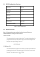
Table Of Contents
- 1 Safety Summary
- 2 Introduction
- 3 Quick Reference
- 4 Operating Instructions
- 4.1 Instrument Hook-Up
- 4.2 Typical Constant Voltage Operation
- 4.3 Setting Current Limit
- 4.4 Typical Constant Current Operation
- 4.5 Constant Voltage/Constant Current Characteristic
- 4.6 Saving the Power Supply’s Current State
- 4.7 Connecting Two Power Supplies in Series
- 4.8 Connecting Two Power Supplies in Parallel
- 5 RS232 Interface
- 6 Maintenance
- 7 Error Messages
- 8 Specifications
- 9 Service Information
- 10 Limited Three-Year Warranty

27
6.4 Instrument Repair Service
Because of the specialized skills and test equipment required for instrument repair
and calibration, many customers prefer to rely upon B&K Precision for this service.
We maintain a network of B&K Precision authorized service agencies for this
purpose. To use this service, even if the instrument is no longer under warranty,
follow the instructions given in the
Warranty Service Instructions
section of this
manual. There is a nominal charge for instruments out of warranty.
7 Error Messages
The following types of errors may occur:
• Self-test errors
• Calibration errors
• Command errors
The first two types of errors are displayed on the voltage display as: Er xx, where xx is
a number. The command errors are sent through the RS232 interface.
7.1 Self-Test Errors
Er 00: EEPROM does not respond
Ee 01: DAC does not respond
Er 02: CV not high
Er 03: CV not low
Er 04: CC not high
Er 05: CC not low
Er 06: ADC does not respond
Er 07: ADC not ready
Er 08: No reference voltage
Er 09: ADC conversion error
Er 10: ADC AVdd< 3.0V
Er 11: ADC AVdd> 3.6V
Er 12: Calibration constants checksum failed
7.2 Calibration Errors
Zero voltage calibration errors