
User guide

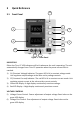
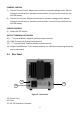
Table Of Contents
- 1 Safety Summary
- 2 Introduction
- 3 Quick Reference
- 4 Operating Instructions
- 4.1 Instrument Hook-Up
- 4.2 Typical Constant Voltage Operation
- 4.3 Setting Current Limit
- 4.4 Typical Constant Current Operation
- 4.5 Constant Voltage/Constant Current Characteristic
- 4.6 Saving the Power Supply’s Current State
- 4.7 Connecting Two Power Supplies in Series
- 4.8 Connecting Two Power Supplies in Parallel
- 5 RS232 Interface
- 6 Maintenance
- 7 Error Messages
- 8 Specifications
- 9 Service Information
- 10 Limited Three-Year Warranty
8
CURRENT CONTROL
7) Current Coarse Control. Adjusts current limit in constant voltage mode. Adjusts
constant current value in constant current mode. Current can be read from the
red LED display.
8) Current Fine Control. Adjusts current limit in constant voltage mode. Adjusts
constant current value in constant current mode. Current can be read from the
red LED display.
POWER CONTROLS
9) Power ON-OFF Switch.
OUTPUT TERMINALS & CONTROL
10) “-” Terminal (Black). Negative polarity output terminal.
11) GND Terminal. Earth and chassis ground.
12) “+” Terminal (Red). Positive polarity output terminal.
13) Output On/Off button. Turns output power on or off without powering down the
entire instrument.
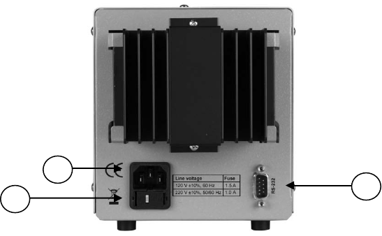
3.2 Rear Panel
Figure 2 - Rear Panel
13) Power Cord
14) Fuse
15) RS-232 Interface Connector
15
14
13