Model 1737 Dual Range DC Power Supply INSTRUCTION MANUAL
1 Safety Summary The following safety precautions apply to both operating and maintenance personnel and must be observed during all phases of operation, service, and repair of this instrument. Before applying power, follow the installation instructions and become familiar with the operating instructions for this instrument. GROUND THE INSTRUMENT To minimize shock hazard, the instrument chassis and cabinet must be connected to an electrical ground.
WARNINGS AND CAUTIONS WARNING and CAUTION statements, such as the following examples, denote a hazard and appear throughout this manual. Follow all instructions contained in these statements. A WARNING statement calls attention to an operating procedure, practice, or condition, which, if not followed correctly, could result in injury or death to personnel.
Compliance Statements Disposal of Old Electrical & Electronic Equipment (Applicable in the European Union and other European countries with separate collection systems) This product is subject to Directive 2002/96/EC of the European Parliament and the Council of the European Union on waste electrical and electronic equipment (WEEE), and in jurisdictions adopting that Directive, is marked as being put on the market after August 13, 2005, and should not be disposed of as unsorted municipal waste.
Contents 1 Safety Summary .......................................................... 1 2 Introduction ................................................................ 5 3 Quick Reference .......................................................... 6 4 5 6 7 3.1 3.2 Front Panel ......................................................................................... 6 Rear Panel .......................................................................................... 7 4.1 4.2 4.3 4.4 4.5 4.6 4.7 4.
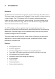
2 Introduction Description The B&K Precision model 1737 is a general purpose dual range DC power source. This power supply can output more voltage at a lower current or more current at a lower voltage. The 1737 provides 0-60 V DC output, adjustable with both coarse and fine voltage controls for precise setting. The current output for the 1737 is 0-3 A for the 0-30 V range, and 0-2 A for the 30-60 V range, adjustable with both coarse and fine current controls.
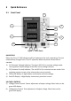
3 Quick Reference 3.1 Front Panel 5 3 1 6 7 4 8 2 9 10 11 12 Figure 1 - Front Panel INDICATORS Either the CV or CC LED indicators will be lit whenever the unit is operating. The unit automatically changes from CV to CC operation when the preset current limit is reached. 1) CV (Constant Voltage) Indicator. The green LED is lit in constant voltage mode. Unit regulates output voltage at the value set by voltage controls. 2) CC (Constant Current) Indicator.
CURRENT CONTROL 7) Current Coarse Control. Coarse adjustment of current limit. Read value on the red LED display. 8) Current Fine Control. Fine adjustment of current limit. Read value on the red LED display. POWER CONTROLS 9) Power ON-OFF Switch. OUTPUT TERMINALS 10) “-” Terminal (Black). Negative polarity output terminal. 11) GND Terminal. Earth and chassis ground. 12) “+” Terminal (Red). Positive polarity output terminal. 3.
4 Operating Instructions Safety Precautions Use only a polarized 3-wire AC outlet. This assures that the power supply chassis, case, and ground terminal are connected to a good earth ground and reduces danger from electrical shock. There is little danger of electrical shock from the power supply output, which produces a maximum of 60 volts dc. However, there may be great danger of electrical shock if the power supply output is connected to an external high voltage.
4.1 Instrument Hook-Up 1. 2. 3. 4. Turn off the power supply and the equipment to be powered during hookup. Connect the positive polarity of the device being powered to the red (+) terminal of the power supply. Connect the negative polarity of the device being powered to the black (-) terminal of the power supply. Figure 3 illustrates the grounding possibilities. a.
Figure 3 (A and B) - Grounding Possibilities Figure 3 (C and D) - Grounding Possibilities 10
4.2 Typical Constant Voltage Operation 1. 2. 3. 4. 5. 6. 7. Before connecting the device to be powered to the power supply, determine the maximum safe load current for the device to be powered and set the current limit value (see Setting Current Limit procedure in this section). The output voltage can be set using the voltage coarse knob (with a 1 V resolution) and voltage fine knob (with a 10 mV resolution). After the last adjustment you must wait 3 seconds until the state is saved.
4.3 Setting Current Limit 1. 2. 3. 4. 5. Determine the maximum safe current for the device to be powered. Temporarily short the (+) and (-) terminals of the power supply together with a test lead. Adjust the coarse and fine current control for the desired current limit. Read the current value on the current LED display. The current limit (overload protection) has now been preset. Do not change the current controls settings after this step.
4.4 Typical Constant Current Operation 1. 2. 3. 4. 5. 6. 7. Before connecting the device to be powered to the power supply, determine the maximum safe voltage to be applied, and set the voltage controls to obtain that voltage reading on the voltage LED display. Determine the desired constant current value. Set the coarse and fine current control to minimum (1 mA). Wait 3 seconds. Turn off the power supply and connect it to the device to be powered. Turn on the power supply. The CC indicator should light.
4.5 Constant Voltage/Constant Current Characteristic The working characteristic of this power supply is called a constant voltage/constant current automatic crossover type. This permits continuous transition from constant current to constant voltage modes in response to the load change. The intersection of constant voltage and constant current modes is called the crossover point. Figure 7 shows the relationship between this crossover point and the load.
4.6 Saving the Power Supply’s Current State The current state of the power supply is saved after 2 seconds from the last adjustment or after the “SAVE” command is received through the RS232 interface. 4.7 Connecting Two Power Supplies in Series Two power supplies may be connected in series to provide a variable 0-120 V output. In this configuration, the two power supplies can supply up to 60 V-3 A or 120 V-2 A. See Figure 8 for the connection scheme.
4.8 Connecting Two Power Supplies in Parallel Two power supplies may be connected in parallel to double the maximum load current. In this configuration, the two power supplies will provide 0-60 V output at up to 4 A or 0-30 V at 6 A (heavier gauge hook-up leads are advisable). Current equalizing resistors must be used as shown in Figure 9. However, the protective current limiting feature will prevent damage if current is temporarily unbalanced during set-up.
If the current equalizing resistors are not well matched, it is preferable that the voltages be slightly unbalanced to achieve current balance. Be sure that the supplies are adequately balanced so that both remain in the CV mode. When connected in parallel and operating in the constant current mode, the voltage controls of both supplies should be preset to the same value.
5.1 RS232 Configuration Overview Baud Rate 9600 bps Parity Bits none Data Bits 8 Start Bits 1 Stop Bits 1 Flow Control Xon / Xoff Termination Character \r Table 1 - RS232 Configuration 5.2 RS232 Commands 1.VOLT xx.xx This command sets the output voltage value. The output voltage takes the programmed value only if the power supply is in Constant Voltage mode. Example: The output voltage is set at 5 V. VOLT 05.00 2. CURR x.xxx This command sets the output current value.
3. SAVE The programmed values of the output current and voltage are saved. If the power supply is restarted, the values of the output current and voltage will be those previously saved. 4. VOLT? This command returns the voltage measured to the output terminals of the power supply: xx.xxV The voltage value returned is the same as the one displayed on the voltage display. 5. CURR? This command returns the current measured to the output terminals of the power supply: x.
6 Maintenance WARNING The following instructions are for use by qualified personnel only. To avoid electrical shock, do not perform any servicing other than contained in the operating instructions unless you are qualified to do so. 6.1 Fuse Replacement If the fuse blows, the CV or CC indicators will not light and the power supply will not operate. The fuse should not normally open unless a problem has developed in the unit.
6.3 Calibration Calibration is a procedure that ensures that the power supply will work properly, with parameters specified within the Specifications section.
1. Turn on the power supply in calibrating mode a) Turn off the power supply. Disconnect the power cord and all loads connected to the power supply. b) Remove power supply’s cover. c) Set the calibration jumper as shown in Figure 11. d) Reassemble the power supply. e) Connect the power cord to the power supply. f) Turn on the power supply in Calibration menu.
2. Zero voltage calibration a) Turn the current coarse knob to select “U 0” for zero voltage calibration and turn the voltage coarse knob. The power supply will display: Voltage display: U 0 Current display: hex number On the current display, a hexadecimal number between 0 and FFFFh is displayed. During the zero voltage calibration, the CV LED is lit. b) Connect a digital voltmeter to the output terminals of the power supply (B&K Precision 5491B or similar instrument).
A hexadecimal number between 0 and FFFFh will be shown on the current display. During the zero voltage calibration, the CV LED is lit. b) Connect a digital voltmeter to the output terminals of the power supply (B&K Precision 5491B or similar instrument). c) Use the current coarse and fine knobs to adjust the value displayed by the power supply until the voltmeter indicates the value to 60.882 V. d) Turn the voltage coarse knob to finish the calibration.
A hexadecimal number between 0 and FFFFh is shown on the current display. c) Use the current coarse and fine knobs to adjust the value displayed by the power supply until the ammeter indicates the closest value to 0 A. d) Turn the voltage coarse knob to finish the calibration. While performing the zero current calibration, the current display will show Adc. After the zero current calibration, the message Done is shown on the current display for 1 sec. Then the power supply returns to the Calibration menu.
A hexadecimal number between 0 and FFFFh is shown on the current display. c) Use the current coarse and fine knobs to adjust the value displayed by the power supply until the ammeter indicates the value to 3.0801 A. d) Turn the voltage coarse knob to finish the calibration. While performing the full current calibration, the current display will show Adc. After the full current calibration, the message Done is shown on the current display for 1 sec.
7 Error Messages The following types of errors may occur: • Self-test errors • Calibration errors • Command errors The first two types of errors are displayed on the voltage display as: Er xx, where xx is a number. The command errors are sent through the RS232 interface. 7.
Full voltage calibration errors: Er 30: CC not high Er 31: CV not low Er 32: DAC out of range Er 33: ADC out of range Er 34: ADC system calibration failed Er 35: DAC full voltage constant checksum failed Er 36: ADC full voltage constant checksum failed Zero current calibration errors: Er 40: CC not low Er 41: CV not high Er 42: DAC out of range Er 43: ADC out of range Er 44: ADC system calibration failed Er 45: DAC zero current constant checksum failed Er 46: ADC zero current constant checksum failed Full c
8 Specifications 1737 Output Ratings ( 0 °C~40 °C) 0-60 V 0-3 A (0-30 V), 0-2 A (30-60 V) Voltage Current Load Regulation ±(% of output+offset) Voltage Current Line Regulation ±(% of output+offset) 0.01% + 3 mV 0.2% + 3 mA Voltage Current Ripple & Noise (20 Hz ~ 20 MHz) 0.01% + 3 mV 0.2% + 3 mA Voltage Current Recovery Time Meter Resolution 1 mVrms ≤ 3 mArms ≤ 100 μs Voltage Current Metering Accuracy 10 mV 1 mA 0.5% + 9 digits 0.
Storage Humidity Mechanical Specifications 85% R.H. 10.5 lbs (4.8 kg) 5.5” x 6.2” x 12.5" (140 x 158 x 318 mm) Power cord, instruction manual, RS-232 cable, shorting bar Weight Dimensions (W x H x D) Supplied Accessories NOTE: All specifications apply to the unit after a temperature stabilization time of 30 minutes. Specifications and information are subject to change without notice. To ensure the most current version of this manual, please download the current version here: http://www.bkprecision.
9 Service Information Warranty Service: Please go to the support and service section on our website at www.bkprecision.com to obtain an RMA #. Return the product in the original packaging with proof of purchase to the address below. Clearly state on the RMA the performance problem and return any leads, probes, connectors, and accessories that you are using with the device. Non-Warranty Service: Please go to the support and service section on our website at www.bkprecision.com to obtain an RMA #.
10 Limited Two-Year Warranty B&K Precision Corp. warrants to the original purchaser that its products and the component parts thereof will be free from defects in workmanship and materials, for a period of two years from date of purchase. B&K Precision Corp. will, without charge, repair or replace, at its option, defective product or component parts. Returned product must be accompanied by proof of the purchase date in the form of a sales receipt. To obtain warranty coverage in the U.S.A.
(Page intentionally left blank) 33
22820 Savi Ranch Parkway Yorba Linda, CA 92887 www.bkprecision.com © 2011 B&K Precision Corp.