INSTRUCTION MANUAL MODEL 1671A INSTRUCTION MANUAL MODEL 1671A Triple Output DC POWER SUPPLY C UL US
TEST INSTRUMENT SAFETY WARNING Normal use of test equipment exposes you to a certain amount of danger from electrical shock because testing must sometimes be performed where exposed high voltage is present. An electrical shock causing 10 milliamps of current to pass through the heart will stop most human heartbeats. Voltage as low as 35 volts dc or ac rms should be considered dangerous and hazardous since it can produce a lethal current under certain conditions. Higher voltages are even more dangerous.
Instruction Manual For Model 1671A Triple Output DC POWER SUPPLY B&K Precision Corporation 22820 Savi Ranch Parkway Yorba Linda, California 92887
TABLE OF CONTENTS Page Page TEST INSTRUMENT SAFETY.........................inside front cover Constant Voltage/Current Characteristics.........................9 INTRODUCTION.........................................................................1 12 Vdc Output...................................................................9 SPECIFICATIONS........................................................................2 5 Vdc Output...................................................................
ii
INTRODUCTION The main output voltage and current are continuously monitored by two digital LCD meters with resolution of 0.1 volt and 0.01 amp. The B+K Precision Model 1671A is a general purpose triple output DC power supply. Their main outputs are versatile constant voltage or constant current regulated power source that is variable from 0 to 30 volts and 0 to 5 amps. An indicator lights in the constant current mode, and serves as an overload indicator in the constant voltage mode.
SPECIFICATIONS CONSTANT CURRENT MODE LOAD REGULATION OUTPUT NO. 1 ≤0.4% + 10 mA VOLTAGE LINE REGULATION (108 TO 132 VAC) Variable 0-30 VDC ≤0.4% + 10 mA RIPPLE AND NOISE CURRENT ≤ 10 mA rms 0 to 5 Amps PROTECTION POLARITY Current limiting, short circuit protection, reverse polarity protection Positive or Negative VOLTAGE INDICATOR CONNECTORS 3 digit LCD Binding Posts VOLTAGE RESOLUTION REGULATION TYPE 0.
SPECIFICATIONS OUTPUT NO. 3 OUTPUT NO.
SPECIFICATIONS COOLING DIMENSIONS (H x W x D) Variable speed thermal static control fan 4.9" x 8.5" x 11.5" (124 x 216 x 292mm) AC INPUT WEIGHT approx. 115/230 VAC, 50/60 Hz~ (~Alternate current) 14.3 lbs (6.5 kg) POWER CONSUMPTION ACCESSORIES SUPPLIED 265W Instruction Manual Spare fuse OPERATION TEMPERATURE 0º TO 40º C, 10-80%R.H.
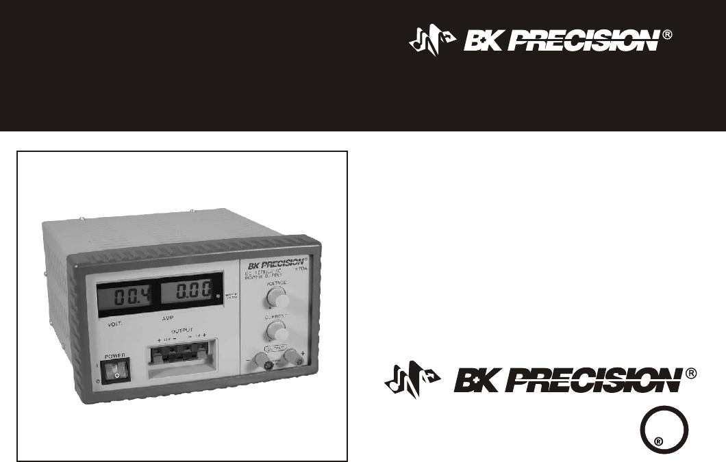
CONTROLS AND INDCATORS 9. OUTPUT - Terminal (Black). Negative polarity variable output terminal. 1. POWER Switch. Turns power supply on and off. "I" : power switch ON "O" : power switch OFF 2. Power ON light. Lights when power is turned on. 10. 12V OUTPUT + Terminal (red). Positive polarity 12 VDC output terminal. 3. CURRENT LIMITED Indicator. Lights when variable supply is operating in constant current mode. 11. 12V OUTPUT - Terminal (black). Negative polarity 12 VDC output terminal. 4.
CONTROLS AND INDICATORS 14 16 15 Figure 1. Front Panel Controls and Indicators, Model 1671A Figure 2.
OPERATING INSTRUCTIONS the vent on top of the power supply. DO NOT place objects on top of the power supply. SAFETY PRECAUTIONS CAUTION Protection provided by the equipment may be impaired if the equipment is used in a manner not specified by the manufacturer Use only a polarized 3-wire outlet.
OPERATING INSTRUCTIONS 2. Connect the red (+) OUTPUT terminal of the power supply to the positive polarity input of the equipment being powered. 3. Connect the black (-) OUTPUT terminal of the power supply to the negative polarity input of the equipment being powered. 4. Place the POWER switch to the ON position, the ON indicator should illuminate, 5. Setting Current Limit 1. Determine the maximum safe current for the device to be powered. 2.
OPERATING INSTRUCTIONS 7. If the load current reaches the constant current value, the CURRENT LIMITED indicator will light. If the load current drops below the constant current value, the CURRENT LIMITED indicator will go off. In this case the power supply automatically switches to the constant voltage mode, and further rotation of the CURRENT control will not increase the output current.
OPERATING INSTRUCTIONS 5 VDC Output DUAL OR TRIPLE OUTPUT The 5 Vdc is a fixed voltage supply providing up to 500 mA (0.5 amp) continuous. The 5 Vdc output is available at the two right OUTPUT 5V tie points. Be sure to observe polarity. Two of the outputs, or all three of the outputs may be used simultaneously if desired. The three outputs are fully isolated from ground, and each other, thus each output may be connected for the either positive or negative polarity. CAUTION 1. 2. 3.
OPERATING INSTRUCTIONS Figure 4. Example of Triple Output Hook-up for +5V, +12V, and -12V Figure 5.
MAINTENANCE INSTRUMENT REPAIR SERVICE WARNING Because of the specialized skills and test equipment required for instrument repair and calibration, many customers prefer to rely upon B & K Precision for this service. We maintenance a network of B+K Precision authorized service agencies for this purpose. To use this service, even if the instrument is no longer under warranty, follow the instructions given in the WARRANTY SERVICE INSTRUCTIONS section of this manual.
Service Information Warranty Service: Please return the product in the original packaging with proof of purchase to the address below. Clearly state in writing the performance problem and return any leads, probes, connectors and accessories that you are using with the device. Non-Warranty Service: Return the product in the original packaging to the address below. Clearly state in writing the performance problem and return any leads, probes, connectors and accessories that you are using with the device.
Limited One-Year Warranty B&K Precision Corp. warrants to the original purchaser that its products and the component parts thereof, will be free from defects in workmanship and materials for a period of one year from date of purchase. B&K Precision Corp. will, without charge, repair or replace, at its option, defective product or component parts. Returned product must be accompanied by proof of the purchase date in the form of a sales receipt. To obtain warranty coverage in the U.S.A.
(Continued from inside front cover) 4. If possible, familiarize yourself with the equipment being tested and the location of its high voltage points. However, remember that high voltage may appear at unexpected points in defective equipment. 5. Use an insulated floor material or a large, insulated floor mat to stand on, and an insulated work surface on which to place equipment; and make certain such surfaces are not damp or wet. 6.
B&K Precision Corporation 22820 Savi Ranch Parkway Yorba Linda, California 92887 www.bkprecision.