
Manual

35
4. Rotate the AC VOLTS control to maximum. The control
should rotate smoothly and the output voltage should
increase smoothly to 150 volts, as read on the meter. TO
check mete calibration, measure voltage with calibrated
external meter at 120 volts and compare reading to front
panel meter.
5. Reduce the voltage to minimum and connect a load to the
ISOLATED OUTPUT. A load consisting of light bulbs
totaling 240 watts is preferred. Set the function switch to
AMPS and increase the AC VOLTS control until the
meter reads 2 amps (or 120 volts, whichever occurs first).
To check meter calibration, measure current with
calibrated external meter at 2.0 amps and compare to front
panel meter.
6. For Model 1655A, check that the meter reads 2 amps on
both the 0-2A and 0-4A range.
7. For Model 1655A, check the leakage function as follows:
a. Reduce the voltage to minimum and connect the
leakage probe to the hot side of the ISOLATED
OUTPUT.
b. Select the LEAKAGE function and slowly
increase the AC VOLTS control until meter reads
500 µA on the leakage scale. This should occur at
about 6 volts. To check meter calibration, measure
leakage current with calibrated external meter and
compare to front panel meter.
c. Increase the AC VOLTS control until the meter
reads 5mA on the leakage scale. This should
occur at about 60 volts. With the reverse polarity
of LEAKAGE function, the meter should read
zero.
d. Change the leakage probe to the common side of
the ISOLATED OUTPUT and select both
polarities of the LEAKAGE function. One
polarity should read zero and the other should
indicate 5mA of leakage.
8. For Model 1655A, check the soldering iron temperature
control function as follows:
a. Connect a load to the soldering iron outlet on the
rear panel. A lamp of 25 to 100 watts is preferred,
or a soldering iron may be used. Turn on the
SOLDER TEMP control. The amber pilot light
should illuminate.
b. Connect an ac voltmeter across the load and vary
the SOLDER TEMP control from minimum to
maximum. At 120 volts line voltage, the light
bulb intensity should vary and the voltmeter
should read from roughly 85 volts at minimum to
118 volts at maximum (this variation will not be
achieved unless a load is connected).
TROUBLESHOOTING
If the previously listed “Performance Tests” are performed in
the sequence listed, this provides a logical approach to defining
symptoms and isolating defective circuitry. The following
information may help further isolate the problem
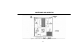
MAINTENANCE AND CALIBRATION