
Manual

34
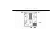
Meter VOLTS Calibration
1. With the power supply turned off, adjust the mechanical
zero of the meter to exact zero.
2. Connect an external multimeter of ±0.5% or better ac
voltage accuracy to the ISOLATED OUTPUT.
3. Turn on the ac power supply and set the AC VOLTS
control for 120 volts on the multimeter
4. Set function switch to VOLTS and adjust VOLTS CAL
(R6 for Model 1653A, R14 for Model 1655A) for 120
volts on built-in meter.
Meter AMPS Calibration
1. Connect a 60 ohm, 240 watt resistive load to the
ISOLATED OUTPUT receptacle. Parallel light bulbs
totaling 240 watts is suitable.
2. Connect a calibrated multimeter of 1% or better ac current
accuracy in series with the load to measure each current.
Set the multimeter to a 2-amp range.
3. Turn on the ac power supply and slowly increase the
output voltage until the multimeter measures 2.0 amps.
4. Set the function switch to AMPS and adjust AMPS CAL
(R7 for Model 1653A, R12 for Model 1655A) for 2.0
amps on the built-in meter.
5. For Model 1655A, adjust calibration on the 0-2A range.
The adjustment calibrates both scales. If 0-4A range is
inaccurate, replace R5 and R6 with matched equal
resistors and repeat calibration adjustment.
Meter LEAKAGE Calibration (Model 1655A only)
1. Connect the leakage probe in series with a 220 kΩ, ¼ watt
resistor.
2. Connect a calibrated multimeter of 1% or better ac current
accuracy in series with the 220kΩ resistor and leakage
probe. Set the multimeter to measure 500µA ac current.
3. Carefully connect the other lead of the multimeter to the
hot side of the ISOLATED OUTPUT receptacle. Adjust
the AC VOLTS control for exactly 500µA on the
multimeter.
4. Select the LEAKAGE function and adjust LEAKAGE
CAL (R11) for 500µA on the built-in meter.
PERFORMANCE TESTS
The following checks test all functions of the ac power supply
for proper operation. The sequence of the checks also provides a
logical symptom and fault isolation technique for troubleshooting.
After troubleshooting and repair, these tests should be performed
to assure that all faults have been corrected.
1. Before the power supply is turned on, the meter should
rest at exact zero. If mechanical zero adjustment is
required, calibration adjustments should be rechecked.
2. Set the POWER ON switch to on. The POWER ON pilot
light should illuminate.
3. Set the function switch to VOLTS and rotate the AC
VOLTS control to minimum (fully counterclockwise).
The output should go to zero as read on the front panel
meter.
MAINTENANCE AND CALIBRATION