
User guide


| 9
Wiring | Zeus Installation Manual
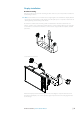
Power Control master/slave bus
Turning on the ‘master’ device turns on connected ‘slave’ devices.
1 Zeus displays
2 Power cable
3 Radar Interface box
4 Sonic Hub
5 Ground wire
6 Positive wire
7 Power control wire
If the left Zeus turns on using the power button and is set as the Power Control Master, it will
output voltage on the Power Control bus to power on the other Zeus, the Radar Interface,
and the SonicHub.
If the right Zeus is set to Power Control Slave, it cannot be powered down using its own
power button, but can be set to standby.
If the left Zeus (Power Control Master) is o , the right Zeus can be turned on using its own
power button, but won’t turn on any other devices.
To turn on all network devices from either Zeus, both devices can be con gured as Power
Control Masters.
Note: If an Zeus has its power state controlled by another device (or ignition switch), it can’t
be totally powered down. It can however enter a standby state to save power. If the power
button is pressed and Power O selected, a message will appear “Preparing to standby…”
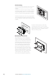
External alarm
Blue wire on power cable:
An external alarm can be connected to one or more Zeus displays on the network. The
external alarm can be a small peizo buzzer connected directly, or a horn siren connected via a
relay.
Alarms are con gured globally in the system i.e they can be con gured on any one
networked multifunction device or Triton instrument, and be seen, heard, and acknowledged
from all devices. Individual devices can also be con gured to not to sound their internal
buzzer, but still display the alarm information. For information on con guring alarms, refer to
the Alarms section in the Operator manual.
+
_
6
3
2
7
8
5
4
1