V9 USER MANUAL Premier Way, Abbey Park Romsey, Hampshire, S051 9DH England Tel: (+44) 01794 518448 Fax: (+44) 01794 518077 www.BandG.com © Brookes & Gatehouse Ltd. 2000 The copyright of this Manual is the property of Brookes & Gatehouse Ltd.
HS 2000 User Manual USER MANUAL CONTENTS Product Liability and Safety Warnings Record of Amendments PART 1 - INTRODUCTION PART 2 - OPERATING INFORMATION PART 3 - CALIBRATION PART 4 - INSTALLATION INFORMATION PART 5 - OPTIONS PART 6 - DIAGNOSTIC DATA APPENDIX 1 CALIBRATION DATA HB-0846-03
HS 2000 User Manual PRODUCT LIABILITY AND SAFETY WARNINGS PRODUCT LIABILITY - Brookes and Gatehouse Ltd. accept no responsibility for the use and/or operation of this equipment. It is the user’s responsibility to ensure that under all circumstances the equipment is used for the purposes for which it has been designed. WARNING - ELECTRICAL HAZARD. This equipment uses high voltage electrical power. Contact with high voltages may result in injury and/or loss of life. WARNING - CALIBRATION.
HS 2000 User Manual RECORD OF AMENDMENTS Date Amendment Number Description Signature HB-0846-03
HS 2000 User Manual Part 1 - Introduction PART 1 - INTRODUCTION CONTENTS Para Page 1.1 SYSTEM DESCRIPTION 1-3 1.2 1.2.1 PROCESSORS Main Processor Unit 1-3 1-3 1.3 1.3.1 1.3.2 1.3.3 1.3.4 1.3.5 SENSORS Paddle-Wheel XTL Fin Sonic Transducers Super Halcyon 3 Fluxgate Compass Halcyon 2000 Fluxgate Compass Depth Sensor 1-4 1-4 1-4 1-5 1-5 1-5 1.4 1.4.1 1.4.2 1.4.3 DISPLAYS NMEA Full Function Display (FFD) Standard Full Function Display (FFD) 20/20 Display 1-5 1-5 1-6 1-6 1.5 CALIBRATION 1-6 1.
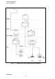
HS 2000 User Manual Part 1 - Introduction Fig 1.
HS 2000 User Manual Part 1 - Introduction PART 1 - INTRODUCTION 1.1 SYSTEM DESCRIPTION The HS 2000 is a fully integrated power boat instrumentation system that displays information obtained from various sensors on a choice of displays positioned throughout the boat. Information is fed from the sensors to a Main Processor via a high speed communications network.
HS 2000 User Manual Part 1 - Introduction The Main Processor Unit contains the battery backed memory that stores all calibration, damping and alarm settings while the power is OFF; these are adjustable from any FFD. 1.3 SENSORS 1.3.1 Paddle-Wheel The Paddle-Wheel Speed Sensor is designed primarily for cruising boats and consists of a paddle-wheel which protrudes through the hull via a hull-housing.
HS 2000 User Manual Part 1 - Introduction 1.3.3 Super Halcyon 3 Fluxgate Compass This fluxgate compass sensor is fully gimballed in a bath of oil, ensuring accurate readings at all normal angles of heel and pitch. 1.3.4 Halcyon 2000 Fluxgate Compass The Halcyon 2000 Compass is a high performance electronic fluxgate compass for use on power craft. It has been designed specifically to connect directly onto the proprietary B&G high speed databus, thus ensuring fast updates and accurate information.
HS 2000 User Manual Part 1 - Introduction The NMEA FFD contains an NMEA interface which enables the HS 2000 to connect to other sensor devices such as position fixers, autopilots, track plotters and radars provided by other manufacturers. For example, information from the GPSplus can be transferred from the bridge to a steering position above decks.
HS 2000 User Manual Part 1 - Introduction Damping should not be confused with the update rate which is the number of times each second that the function value is sent to the display. This update rate is fixed for all functions. 1.7 MENU STRUCTURE The central concept to the operation of the system is the structure of the Function Menus accessed through the FFD; once these are understood operation becomes simple. Regular users of computers will be familiar with the concept of structured menu layers.
HS 2000 User Manual Part 1 - Introduction Table 1.1 - Function Menu Choices FUNCTION MENU CHOICE FUNCTION TEXT Speed Boat Speed Average Speed Stored Log Trip Log Depth - Meters Depth - Feet Depth - Fathoms Heading Off Course Dead Reckoning Course Dead Reckoning Distance Tidal Set Tidal Drift Bearing Waypoint to Waypoint ?Mag. Bearing Waypoint to Waypoint ?True Bearing to Waypoint Rhumb ?Mag. Bearing to Waypoint Rhumb ?True Bearing to Waypoint Great Circle ?Mag.
HS 2000 User Manual Part 1 - Introduction Table 1.
HS 2000 User Manual Part 2 - Operating Information PART 2 - OPERATING INFORMATION CONTENTS Para Page 2.1 2.1.1 2.1.2 2.1.3 2.1.4 2.1.5 2.1.6 2.1.7 2.1.8 2.1.9 FULL FUNCTION DISPLAY (FFD) The Keys On/Off Illumination Key Page Key Scroll Keys Enter/Reset Key Speed/Depth (SPD/DEP) Key Navigation (NAV) Key Temperature (TEMP) Key Remote Push-Button Operation 2-3 2-3 2-4 2-4 2-4 2-5 2-5 2-5 2-6 2-6 2.2 20/20 DISPLAY 2-6 2.3 SUPER HALCYON 3 AND HALCYON 2000 COMPASS 2-6 2.4 2.4.1 2.4.2 2.4.3 2.4.
HS 2000 User Manual Part 2 - Operating Information CONTENTS (Contd) Para Page 2.8 2.8.1 2.8.2 LIGHTING CONTROL Select Local Control Select System Control 2-14 2-14 2-14 2.9 OPERATING NOTES 2-15 2.10 2.10.1 2.10.2 2.10.3 2.10.4 2.10.5 2.10.6 2.10.7 2.10.8 2.10.9 2.10.10 2.10.11 2.10.12 2.10.13 2.10.14 2.10.15 2.10.16 2.10.
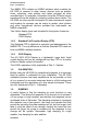
HS 2000 User Manual Part 2 - Operating Information PART 2 - OPERATING INFORMATION 2.1 FULL FUNCTION DISPLAY (FFD) The HS 2000 System is operated by using the keys on any one of the NMEA or Standard Full Function Displays (FFD). Fig 2.1 - Full Function Display The information displayed on each FFD consists of a page of information comprising an upper display and a lower display. The user has four pages which may be configured to display any available function in either the upper or lower displays.
HS 2000 User Manual Part 2 - Operating Information 2.1.2 On/Off Illumination Key This key controls the application of power to the system and the level of illumination at all displays. One short press of this key applies power to the HS 2000 System and the display is activated. A second short press of the key provides full background illumination on all system displays. Further short presses of the key decrease the illumination in three stages from full brightness to OFF.
HS 2000 User Manual Part 2 - Operating Information After a specific page has been selected, pressing the Scroll Up Key selects the upper display. Similarly, operation of the Scroll Down Key selects the lower display. 2.1.5 Enter/Reset Key The principle use of the Enter Key is to invoke selections chosen from the menu by the Scroll Keys. As a general rule, when any menu choice is flashing, pressing the Enter Key will select that choice. The Enter Key is also used to: (a) Enter Data.
HS 2000 User Manual Part 2 - Operating Information Current Heading/Course Over Ground Current Heading/Boat Speed Distance to Waypoint/Bearing to Waypoint Note The NAV key may be configured to show waypoint information in either Great Circle or Rhumb modes. Refer to section 2.4.3 for further details. 2.1.8 Temperature (TEMP) Key By pressing the TEMP key the user is able to select any one of two factory set displays accessing the temperature functions.
HS 2000 User Manual Part 2 - Operating Information selected for display on any of the FFDs or the Halcyon Display. In addition analogue compass card type displays may be added. Note Analogue displays require an additional Wind Board (402-10-005) to be installed in the processor box. Software incorporated with the compass allows the compass to learn the magnetic fields in the vessel which may cause deviation errors.
HS 2000 User Manual Part 2 - Operating Information 2.4.2 Page Display Configuration To store the setting in Paragraph 2.5.1 as a permanent new page, proceed as follows: (1) Press Scroll Up or Scroll Down and scroll text until CNFG DSP is shown on the display. Note Scroll Up or Scroll Down can be used because we are configuring the whole page; both upper and lower displays. (2) Press Enter, PAGE is shown on the lower display.
HS 2000 User Manual Part 2 - Operating Information Our second example is the entry of a damping value. To ascertain whether it is possible to damp a function, you should check the table in Paragraph 2.10 - Operating Functions. (1) Using the Scroll Up or Scroll Down Key select the upper or lower display as required. (2) If BOAT SPD is shown in the upper display, press and hold Scroll Down and scroll to DAMPING, which flashes. If BOAT SPD is shown in the lower display, use Scroll Up.
HS 2000 User Manual Part 2 - Operating Information 2.5 EXAMPLES OF CALIBRATION The method of calibration of your HS 2000 System should be made clear by the following examples. The Calibration Process is described in detail in Part 3 - Calibration. 2.5.1 Calibration Adjustment - Boat Speed (1) Using the Scroll Up or Scroll Down Keys select the upper or lower display as required.
HS 2000 User Manual Part 2 - Operating Information DATUM is referenced to the keel line, the value is negative, which is indicated by a minus sign before the left hand digit. (7) Press Enter to input the new DATUM value into the system. (8) Press Page to return to the normal display. 2.6 ALARMS 2.6.1 Alarm Control When a pre-set alarm parameter is reached, for example, the depth reducing, the system raises an alarm automatically.
HS 2000 User Manual Part 2 - Operating Information For example, when the SECTOR alarm is turned on, the alarm reference heading is the current compass heading. If the SECTOR alarm is set at 40°, the sector value is the compass heading +/- 20°. It is therefore important to switch off the SECTOR alarm before carrying out a course alteration and switching the alarm on again when settled on the new course heading. Any alarm can be turned ON and OFF individually, or all alarms can be turned OFF collectively. 2.
HS 2000 User Manual Part 2 - Operating Information 2.6.5 Disable Alarms (1) Select any function with an alarm facility, for example, DEPTH. (2) If function is in the upper display, press Scroll Down to scroll to ALARMS, or if function is on the lower display use the Scroll Up Key. Then press Enter, ALL OFF appears flashing. (3) Press Enter again, all alarms are turned OFF and the normal page display will be restored.
HS 2000 User Manual Part 2 - Operating Information (2) Press Scroll Down once and the lower text now shows CONTROL flashing. (3) Press Enter and use the Scroll Down key to display RESET flashing. (4) Press the Enter key and the display now shows RUN flashing. (5) Press the Enter key again and the display shows the trip log running. (6) Press the Page key to resume normal operation. Note Each time you reset the TRIP LOG the AVERAGE SPEED resets and begins its calculation again.
HS 2000 User Manual Part 2 - Operating Information (3) Press Enter again, the original page display appears and the illumination control has returned to System Control. Note In order to control the lighting on analogue repeaters, at least one FFD must be set to System Control. 2.9 OPERATING NOTES Within the foregoing paragraphs of this part of the Manual the steps necessary to select a specific function and/or set-up the system have been described in detail.
HS 2000 User Manual Part 2 - Operating Information 2.10.2 Bearing to Waypoint Menu Heading: Function Text: Update Rate: Units: WAYPOINT BTW RMB or BTW GC Provided by position fixer Degrees magnetic, degrees true Notes 1. Requires interfaced position fixing system. 2. Rhumb, Great Circle, Magnetic or True. Once the position fixer is connected and sending information, it automatically appears in the menu and becomes available for display. 2.10.
HS 2000 User Manual Part 2 - Operating Information increased to smooth out the display value in rough conditions or conversely, reduced to accelerate the response in light conditions. 2.10.5 Course Over Ground Menu Heading: Function Text: Update Rate: Units: WAYPOINT CRSE O/G Provided by position fixer Degrees magnetic, true Note Requires interfaced position fixer. Once the position fixer is connected and sending information it automatically appears in the menu and becomes available for display.
HS 2000 User Manual Part 2 - Operating Information Fig. 2.
HS 2000 User Manual Part 2 - Operating Information 2.10.7 Depth Menu Heading: Function Text: Update Rate: Units: DEPTH DEPTH Once per second Metres, feet and fathoms Note Audible, shallow/deep alarm available: Shallow range 0-99.9m Deep range unlimited Depth is one of the most important functions on the boat, being an essential navigational and safety tool. A datum adjustment allows you to move the base point to give either depth under the keel or actual water depth (see Paragraph 2.5.2).
HS 2000 User Manual Part 2 - Operating Information 2.10.9 Heading Menu Heading: Function Text: Update Rate: Units: NAVIGATE HEADING Twice per second Degrees magnetic Notes 1. Adjustable damping, 0-99 sec. 2. Sector alarm available. 3. Sensor alignment calibration. This is the compass heading, derived directly from the electronic Fluxgate Compass; a basic input for the system that allows calculation of dead reckoning and other course related navigation functions.
HS 2000 User Manual Part 2 - Operating Information 2.10.12 Sea Temperature Menu Heading: Function Text: Update Rate: Units: TEMP SEA TEMP Once per second Degrees Centigrade, Fahrenheit 1. Notes Requires temperature sensor. 2. Audible high/low alarm available. Knowledge of sea temperature is useful on long voyages when ocean currents are determined by changes in water temperature. Temperature can also be useful when in the vicinity of river outlets.
HS 2000 User Manual Part 2 - Operating Information 2.10.15 Tidal Set and Drift Menu Heading: Function Text: Update Rate: Units: NAVIGATE TIDE SET or TIDE RTE Once per second Degrees magnetic, knots Notes 1. Damping 0-99 minutes. 2. Calibration: Magnetic variation. 3. Some position fixers output the current local magnetic variation on the NMEA 0183 port using either HVD, HVM, RMA or RMC sentences. As a result CAL VAL 1 on the TIDE SET function will automatically set to the correct variation.
HS 2000 User Manual Part 2 - Operating Information 2.10.16 Time to Waypoint Menu Heading: Function Text: Update Rate: Units: WAYPOINT ETA WPT Provided by position fixer Hours, minutes Notes 1. Also gives ETA. 2. Requires interfaced position fixing system. This is calculated directly by the position fixer and is based on your speed over the ground towards the mark which it assumes will be constant. 2.10.
HS 2000 User Manual Part 3 - Calibration PART 3 - CALIBRATION CONTENTS Para Page 3.1 INTRODUCTION 3-3 3.2 3.2.1 3.2.2 3.2.3 3.2.4 3.2.5 3.2.6 3.2.7 3.2.8 BOAT SPEED/LOG CALIBRATION Principle of Log Calibration Preparation for Log Calibration Calibration Runs Log AUTO CAL Facility Log AUTO CAL Procedure Manual Calibration Speed Calibration Referenced to a Known Value Boat Speed Calibration 3-3 3-3 3-3 3-4 3-4 3-5 3-6 3-6 3-6 3.3 3.3.1 3.3.2 3.3.3 3.3.
HS 2000 User Manual Part 3 - Calibration Intentionally Left Blank HB-0846-03 3-2
HS 2000 User Manual Part 3 - Calibration PART 3 - CALIBRATION 3.1 INTRODUCTION WARNING - Every care must be taken when undertaking any calibration procedure to ensure that the HS 2000 System is calibrated accurately and correctly. Incorrect calibration could lead to incorrect navigational information. Calibration of an integrated instrument system is one of the most misunderstood processes. Good instruments badly calibrated will achieve very little.
HS 2000 User Manual Part 3 - Calibration 3.2.3 Calibration Runs Consecutive runs at a constant speed should be made over a known distance. To eliminate the effect of tidal conditions, it is advisable to perform at least two runs, preferably three, along the measured track. There are three available options for calibrating the log; Automatically (AUTO CAL), Manually (MANL CAL) or Reference (REF CAL). 3.2.
HS 2000 User Manual Part 3 - Calibration 3.2.5 Log AUTO CAL Procedure (1) Select BOAT SPD on the display. (2) If BOAT SPD is in the upper display, press and hold Scroll Down to select CALBRATE. If BOAT SPD is in lower display, use Scroll Up to select CALBRATE. (3) Press Enter, the display shows the current boat speed reading with AUTO CAL flashing. (4) Press Enter, the display shows the current boat speed reading with SINGLE flashing.
HS 2000 User Manual Part 3 - Calibration 3.2.6 Manual Calibration The calibration values can be adjusted directly as shown in ‘Examples of Calibration’ included in Part 2 - Operating Information. 3.2.7 Speed Calibration Referenced to a Known Value The following enhancement is only available when HS 2000 speed/depth computer is used in conjunction with an HS 2000 FFD Display with a software version later than 5C.
HS 2000 User Manual Part 3 - Calibration (6) Press Enter, the lower text now shows CAL VAL 1 flashing. (7) Press Scroll Down repeatedly, and the lower text will cycle through CAL1 VAL 1, CAL VAL 2, and CAL VAL 3 When CAL VAL 1 is displayed: (8) Press Enter, the lower text shows SPD KTS. When CAL VAL 2 is displayed: (9) Press Enter, the lower text shows SPD MPH. When CAL VAL 3 is displayed: (10) Press Enter, the lower text shows SPD KPH.
HS 2000 User Manual Part 3 - Calibration (d) The rate of change in heading is constant. (e) Automatic calibration has been utilised by connecting the brown wire from the compass at the junction box (Super Halcyon 3 only). (f) The compass is installed in a location free from magnetic interference such as iron keels, engines, loudspeakers etc. Consideration should also be given to electrical cables which may carry excessive currents (e.g. navigation lights).
HS 2000 User Manual Part 3 - Calibration (3) Press the Scroll Up key again until the display shows D/R CRSE ?M flashing. (4) Press Enter. D/R CRSE ?M will now stop flashing. (5) Press Scroll Down until the display shows CALBRATE. (6) Press Enter 3 times. The display now shows HDG NODE and will display a value which flashes. (7) Use the Scroll Up and Scroll Down keys to change the value to the required setting. (8) Press Enter.
HS 2000 User Manual Part 3 - Calibration compass display should considerably assist the helmsman in monitoring the rate of turn. The rate of turn is indicated on the Halcyon Display. (5) When the compass has completed its calibration, the displayed heading will rotate in the opposite direction for 360° and settle on the correct bearing to indicate the calibration is complete. You should continue to turn until you see this.
HS 2000 User Manual Part 3 - Calibration (7) Press the Enter key once and the ‘0’ starts to flash. Use the Scroll Up key to change the value to ‘1’. (8) Press the Enter key. The display now shows 000?. (9) At a speed not exceeding five knots, turn the boat through 360? at a rate not greater than 2-3? per second. The display will show the amount of turn completed so far. Continue to turn the boat until the display shows PASS or FAIL. Notes 1. The compass calibration swing may be aborted at any time.
HS 2000 User Manual Part 3 - Calibration 3.4 DEPTH CALIBRATION A typical transducer installation is through the hull at a suitable position between the water line and the bottom of the keel. A DATUM (offset value) can be set, such that the depth display refers to either the water line or the keel line. Fig 3.2 - Depth Datum The datum is entered under: DEPTH ? DEPTH, CALBRATE ? DATUM 3.
HS 2000 User Manual Part 3 - Calibration 3.5.1 Sea Temperature Offset Calibration To calibrate SEA TEMP C or SEA TEMP F proceed as follows: (1) Select SEA TEMP C on upper half on FFD display. (2) Press Scroll Down until the lower text shows CALIBRATE flashing. (3) Press Enter, the lower text now shows CAL VAL 1 flashing. (4) Press Scroll Down, the lower text now shows CAL VAL 2 flashing. (5) Press Enter, the lower text now shows OFFSET C.
HS 2000 User Manual Part 4 - Installation Information PART 4 - INSTALLATION INFORMATION CONTENTS Para Page 4.1 INTRODUCTION 4-3 4.
HS 2000 User Manual Part 4 - Installation Information Intentionally Left Blank HB-0846-03 4-2
HS 2000 User Manual Part 4 - Installation Information PART 4 - INSTALLATION INFORMATION 4.1 INTRODUCTION This part of the manual contains information relating to the interconnection of the units that make up the HS 2000 system. It is provided to enable qualified technicians to fault find or undertake the installation of additional units and thereby increase the number of functions available.
HS 2000 User Manual Part 4 - Installation Information 4.
HS 2000 User Manual Part 4 - Installation Information HB-0846-03 4-5
HS 2000 User Manual Part 4 - Installation Information HB-0846-03 4-6
HS 2000 User Manual Part 4 - Installation Information HB-0846-03 4-7
HS 2000 User Manual Part 4 - Installation Information HB-0846-03 4-8
HS 2000 User Manual Part 4 - Installation Information HB-0846-03 4-9
HS 2000 User Manual Part 4 - Installation Information HB-0846-03 4-10
HS 2000 User Manual Part 4 - Installation Information HB-0846-03 4-11
HS 2000 User Manual Part 4 - Installation Information 8-BUTTON NMEA FULL FUNCTION DISPLAY INSTALLATION SHEET NMEA FFD CABLE FUNCTION Network Data -ve Network Data +ve Network Cable Shield Ground Supply +ve NMEA Input Signal NMEA Input Return NMEA Output Signal Remote Control Button FFD CABLE COLOUR Green White Shield Black Red Brown Blue Violet Yellow SYSTEM NETWORK Green White Shield Black Red - NMEA INPUT Red Blue - NMEA OUTPUT Shield Blue Red - REMOTE BUTTON Blue Red INSTALLATION NOTES ?? An NMEA
HS 2000 User Manual Part 4 - Installation Information 8 BUTTON FULL FUNCTION DISPLAY WIRING DETAILS FFD CABLE FUNCTION Network Data -ve Network Data +ve Network Cable Shield Ground Supply +ve Remote Control Button Not used FFD CABLE COLOUR Green White Shield Black Red Yellow Brown SYSTEM NETWORK Green White Shield Black Red - REMOTE BUTTON Blue Red - INSTALLATION NOTES FOR HS 2000 ?? The system requires at least one FFD. ?? An FFD can be connected at any point on the system network.
HS 2000 User Manual Part 4 - Installation Information HB-0846-03 4-14
HS 2000 User Manual Part 5 - Options PART 5 - OPTIONS CONTENTS Para Page 5.1 SYSTEM EXPANSION 5-3 5.2 AUDIBLE ALARM 5-3 5.3 5.3.1 5.3.2 5.3.3 5.3.4 5.3.5 20/20 DISPLAY The Display Display Configuration Function Selection - Remote Push-Button Function Selection FFD Re-configuring 20/20 Display 5-3 5-3 5-4 5-4 5-4 5-5 5.4 5.4.1 5.4.2 5.4.3 5.4.4 5.4.5 5.4.6 5.4.7 5.4.8 5.4.
HS 2000 User Manual Part 5 - Options Intentionally Left Blank HB-0846-03 5-2
HS 2000 User Manual Part 5 - Options PART 5 - OPTIONS 5.1 SYSTEM EXPANSION The HS 2000 System can be expanded to provide a wider range of facilities and features by the addition of further displays, sensors, and interfaces. These options are described in the following paragraphs. 5.2 AUDIBLE ALARM The Main Processor contains a relay switch for an external audible alarm. 5.3 20/20 DISPLAY 5.3.
HS 2000 User Manual Part 5 - Options 5.3.2 Display Configuration The 20/20 can be configured to display any function available on your HS 2000 System. It is, however, provided with 14 pre-set functions which may be selected by use of a Remote Push-Button connected to the display or via any FFD on the system.
HS 2000 User Manual Part 5 - Options (2) Using the Scroll Down Key cycle through the 20/20 numbers and select the required Display Number. (3) Using the Scroll Up Key cycle through the 14 pre-set functions until the required function is displayed on the FFD. Release the Scroll Up Key. (4) If the function is missed, press and hold down the Scroll Up Key and the functions will cycle through in reverse order. Release the Scroll Up Key when the required function is displayed. (5) Press the Page Key.
HS 2000 User Manual Part 5 - Options 5.4 HALCYON DISPLAY The Halcyon Display is a dedicated electronic compass display which may be connected to your HS 2000 System in a similar manner to an FFD. The display provides clear and accurate digital indication of compass heading information together with a bar graph indicating port and starboard off-course error relative to a set course. The display area is split into three. The three large digits in the upper left part always show compass heading.
HS 2000 User Manual Part 5 - Options 5.4.1 The Keys The Halcyon Display is provided with the following five keys: Power/Lights Key Page Key Scroll Up Key Scroll Down Key Enter Key 5.4.2 Power/Lights Key The Power/Lights Key is operated in an identical manner to the Power/Lights Keys provided on the FFDs. See Part 2 - Operating Information. 5.4.3 Page Key Successive pressing of the Page Key will access the following three functions in a fixed order: ?? Off Course ?? Stored Course ?? Turn Rate 5.4.
HS 2000 User Manual Part 5 - Options (3) Press the Scroll Down key until the display shows POWER BOAT. (4) Press the Page key to exit the setup mode. The Halcyon Display has now been configured for Cruise Power operation. 5.4.5 Off Course Function The Off Course function provides the helmsman with accurate Off Course information to assist in steering a steady and accurate course. Off Course is calculated by comparing the vessel’s current heading with a previously set reference heading.
HS 2000 User Manual Part 5 - Options To select a specific course number proceed as follows: (1) Select the Stored Course Function by successive presses of the Page Key until the display shows the Stored Course Function. (2) Press Scroll Up and CRS 1 will flash. (3) Using the Scroll Up and/or Scroll Down Keys select the course (CRS) number required. (4) Press the Enter Key to enter the selected course as the reference.
HS 2000 User Manual Part 5 - Options 5.4.9 Instantaneous Rate While the Halcyon Display is showing the vessel’s mean rate of turn, press the Scroll Down key, the DEG/S legend is shown to indicate rate of turn displayed as degrees per second. The centre analogue bar graph will now show the instantaneous rate of turn to port or starboard.
HS 2000 User Manual Part 6 - Diagnostic Data PART 6 - DIAGNOSTIC DATA CONTENTS Para Page 6.1 6.1.1 6.1.2 6.1.3 6.1.4 6.1.5 6.1.6 6.1.7 6.1.8 6.1.9 6.1.10 6.1.11 6.1.12 6.1.13 FFD DIAGNOSTICS Diagnostic Function Selection Key Test Display Network RAM PROM EPROM Lighting Debug RES-SYS Versions Errors Remote 6-3 6-3 6-3 6-4 6-4 6-4 6-4 6-4 6-5 6-5 6-5 6-5 6-6 6-6 6.2 6.2.1 6.2.2 6.2.3 6.2.
HS 2000 User Manual Part 6 -Diagnostic Data Intentionally Left Blank HB-0846-03 6-2
HS 2000 User Manual Part 6 - Diagnostic Data PART 6 - DIAGNOSTIC DATA 6.1 FFD DIAGNOSTICS The FFD program contains a number of diagnostic functions which allow the FFD keys, display and memory to be tested, and also performs checks on other components of the system via the network. One of the more useful of these tests enables the user to determine the software version numbers of the processor units in the system. This information is useful when liaising with Service Agents. 6.1.
HS 2000 User Manual Part 6 -Diagnostic Data If the key operation is not detected after a short interval then the message TIME OUT is displayed. 6.1.3 Display The Scroll Up Key can be used to step the display through a sequence that switches ON single segments in all characters, blanks the display and switches ON all segments. When all segments are switched ON, 16 characters are displayed at the top and bottom of the display.
HS 2000 User Manual Part 6 - Diagnostic Data 6.1.8 Lighting This option checks for correct operation of the display lighting control. 6.1.9 Debug CAUTION: This test is not for normal use, since it may seriously affect the operation of the HS 2000 System. This option is used for accessing memory in other units in the system. 6.1.10 RES-SYS CAUTION: Do not use this option during normal operation as the system will give inaccurate results until re-calibrated.
HS 2000 User Manual Part 6 -Diagnostic Data 6.1.12 Errors This option is primarily used to interrogate the HS 2000 network and is designed for use by service technicians to ascertain levels of interference that may be present, for example, interference may be induced by an SSB transmitter or radar. The display shows the number of messages that have not been transmitted correctly in the first instance; between 10 and 20 errors per minute is quite normal.
HS 2000 User Manual Part 6 - Diagnostic Data All of these symptoms can be caused by external conditions, so care and additional tests should be performed before concluding that the fault lies with the Depth Sounder. Two Depth Sounder parameters which can assist in diagnosing faults are measurements of receiver gain and noise; these can be found in the PARAMTR Menu on any FFD. 6.2.
HS 2000 User Manual Part 6 -Diagnostic Data 6.2.2 Boat Moving Symptom: Display shows: -when boat is moving; this is most often an indication of difficult sounding conditions, but can also indicate a badly positioned transducer. Possible causes: (a) Difficult sounding conditions and/or Depth Sounder unable to track rapidly changing bottom. If entering shallow water, the boat should slow down and proceed with caution. (b) Aeration in the water.
HS 2000 User Manual Part 6 - Diagnostic Data 6.2.3 Consistently Shows Shallow Depth Symptom: Display consistently shows a shallow depth between 0 and about 1.5m. Possible causes: (a) Faulty transducer. The transducer rings for too long after the transmit pulse is sent and the ringing is interpreted as a shallow return by the Depth Sounder. On a deep keeled boat it may be possible to overcome this problem by increasing the minimum depth to just less than the draft of the yacht.
HS 2000 User Manual Part 6 -Diagnostic Data will only occur when other boats are in the close vicinity, for example, when moored alongside in a crowded marina. Furthermore, acoustic noise can be generated by water flow past the transducer and other items of mechanical machinery. (c) Mid-water echoes. When outside the range of the Depth Sounder, it is possible that random depths are displayed due to mid-water echoes from shoals of fish or aeration layers. 6.
HS 2000 User Manual Part 6 - Diagnostic Data 6.4 HALCYON 2000 COMPASS 6.4.1 Shows Heading and CAL Flashing Symptom: Display flashes a Heading and CAL Possible Causes: (a) The memory in the Halcyon 2000 is empty or has been corrupted. This may be due to a System Reset being performed or the first time the compass has been installed and not yet been calibrated. Perform a calibration swing to restore normal operation. (b) After a calibration swing the result is always FAIL.
HS 2000 User Manual Part 6 -Diagnostic Data 6.4.4 Two Headings Flashing Alternately Symptom: Pilot or Halcyon Displays shows 2 headings flashing alternately Possible Causes: (a) The Pilot has not been set to use the Halcyon 2000 as it’s heading source. See using Halcyon 2000 with a B&G ACP Pilot. If the Halcyon 2000 is not to be the source of heading then it must be unplugged from the network. 6.4.
HS 2000 User Manual Part 6 - Diagnostic Data 6.5 NMEA ALPHABETICAL INDEX 6.5.
HS 2000 User Manual Part 6 -Diagnostic Data 6.5.
HS 2000 User Manual Appendix 1 A1 HS 2000 CALIBRATION DATA A1.