
Install guide
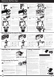

CAUTION: The OPERATE button will not function until
the open and close limit positions are set.
NOTE: The door and shuttle must be engaged into the chain index. The door
should be open approximately half way.
a. Remove the controls cover to access the controls panel using a blade
screwdriver. Refit it when setup is completed.
b. Press and hold the MINUS (-) button to start the door closing. Release the
button once you have reached your desired closed limit position.
c. Press the LIMIT SET button. This action will store the close limit position into
memory.
d. Press and hold the PLUS (+) button to start the door opening. Release the
button once you have reached your desired open limit position.
e. Read the WARNING below.
WARNING! The garage door will automatically close, open and
close again once the LIMIT SET button is pressed. Ensure there
are no persons or objects in the door’s path before pressing the
LIMIT SET button.
f. Press the LIMIT SET button to store into memory the open limit position. The
door will now automatically close to its limit position then fully open to calculate
the Safety Obstruction Forces. Take note of THE ABOVE WARNING!
The opener can now be operated via the OPERATE button.
Adjusting the Speed Setting
The default speed of the opener has been set to suit the majority of applications.
However, there are three speed modes available if required:-
1. Slow - to suit one piece door without tracks
2. Medium ( default ) - suits majority of applications
3. Fast - to suit some sectional applications
Proceed to Programming the Opener if the default setting is appropriate. To change
the Speed Setting;
The speed settings can only be changed before setting the travel limits. If the opener
speed needs to be changed please complete the following process. Pressing the
operate button will cycle through all three speed modes.
To change the speed setting:
a. Engage the C-Rail’s trolley (attached to the door via the arms) with the chain
index by moving the door.
b. If the trolley does not “click” firmly onto the chain index, ensure that the manual
release cord is not in the disengaged position by pulling it backwards.
c. Turn on the power to the opener. The CLOSE LIMIT LED will be flashing.
d. Remove the button cover with a blade screwdriver.
e. Press operate button once, twice or three times to select slow, medium or fast
speed mode.
Door Opener
Speed Mode
OPEN LED
(Green)
CLOSE LED
(Red)
Beeper
Medium ( Default ) On On 2 beeps
Fast On Off 3 beeps
Slow Off On 1 beep
Use blade screwdriver
to remove cover
Programming the Opener
Resetting the Door Limit Positions
To enter new limit positions the existing settings must be deleted
as follows:
a. Press and hold the LIMIT SET button for six (6) seconds, until
you hear three beeps and the CLOSE LIMIT LED starts to
flash.
b. Release the button.
c. Follow Programming the Opener steps to set new limit
positions.
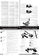
Determine the Door Type
a. Open the door and find the highest point
of travel of the top door panel.
b. Using a level, transfer this height to the
wall above the door and mark a line
60mm above it.
WARNING! Make sure concrete,
brick wall or timber lintels are solid
and sound so as to form a secure
mounting platform.
c. Determine the centre point on the wall
above and on top of the door. Draw two
lines extending 21.5mm (43mm in total)
from each side of the centre point.
d. Centre the bracket over the intersection
of these two lines. Mark centres for holes.
e. Drill holes into wall and secure as follows:
IF CONCRETE OR BRICK
8mm drill bit for holes
8mm (5/6”) loxins / dynabolts to secure
IF TIMBER
min. 50mm wood screw or similar to
secure
f. Leave the drive unit in its packing box on
the floor for protection and lift the other
end of the C-Rail.
g. Attach the C-Rail assembly
16
to the wall
bracket
6
with the 90mm long clevis
pin
11
and secure with the supplied
snap pin
9
.
h. Raise the drive unit from the packing box
and support it in the horizontal position
with a step ladder.
i. Line up the track perpendicular to the
wall.
j. Secure the perforated angle (not supplied)
to the ceiling above where drive unit’s
mounting holes will be once fully installed.
k. Connect the drive unit to the ceiling
mounted perforated angle with M8x20mm
screws and nuts (not supplied). Strips
should not extend more than 18mm
below centre of drive unit mounting holes.
l. To prevent moisture on the C-rail running
into the powerhead it is recommended a
strip of silicon sealant is placed across the
top of the C-rail just before the opener.
Sectional door with track /
B&D Flex-A-Door
®
One piece door with track
(T-Type)
One piece door without track
(Tilt Door / J-Type)
Highest point of
travel
a. Open the door and find the highest point
of travel of the top door panel.
b. Using a level, transfer this height to the
wall above the door and mark a line
60mm above it.
WARNING! Make sure concrete,
brick wall or timber lintels are solid
and sound so as to form a secure
mounting platform.
c. Determine the centre point on the wall
above and on top of the door. Draw two
lines extending 21.5mm (43mm in total)
from each side of the centre point.
d. Centre the bracket over the intersection
of these two lines. Mark centres for holes.
e. Drill holes into wall and secure as follows:
IF CONCRETE OR BRICK
8mm drill bit for holes
8mm (5/6”) loxins / dynabolts to secure
IF TIMBER
min. 50mm wood screw or similar to
secure
f. Leave the drive unit in its packing box on
the floor for protection and lift the other
end of the C-Rail.
g. Attach the C-Rail assembly
16
to the wall
bracket
6
with the 90mm long clevis
pin
11
and secure with the supplied
snap pin
9
.
h. Raise the drive unit from the packing box
and support it in the horizontal position
with a step ladder.
i. Line up the track perpendicular to the
wall.
j. Secure the perforated angle (not supplied)
to the ceiling above where drive unit’s
mounting holes will be once fully installed.
k. Connect the drive unit to the ceiling
mounted perforated angle with M8x20mm
screws and nuts (not supplied). Strips
should not extend more than 18mm
below centre of drive unit mounting holes.
l. To prevent moisture on the C-rail running
into the powerhead it is recommended a
strip of silicon sealant is placed across the
top of the C-rail just before the opener.
Drilled holes
Structural
member
43mm
21.5
Track
Level
Door
60mm
Step
ladder
perforated
angle
perforated
angle
11
16
9
6
Track
Level
Door
60mm
Mounting Door Bracket & Arms
a. The door bracket locator
7
is placed
over the door bracket
8
, on the door’s
centre line one-third down the top panel
and mounted using M6 or equivalent
screws (not supplied),
b. STEEL DOORS ONLY: Bracket can be
welded in place.
NOTE: If in doubt about the door’s
strength, reinforcement may be added to
the door’s frame where necessary. Door
damage may occur if the bracket is installed
on a panel with insufficient strength. The
opener’s warranty does not cover damage
caused to the door and/or door panels.
c. Assemble the bent arm
4
(connecting to
the door) to the right side of the straight
arm
5
(connecting to the shuttle) with
bolts
10
and nuts
13
supplied in the
accessory pack. Always use both bent
and straight arms.
d. Connect the assembled arm to the
bracket and the disengaged trolley with
clevis
12
and snap pins
9
. The angle
“A” must be more than 10°.
12
8
7
13
10
9
10
0
A
Bent Arm closest
to the door
a. Mount the door bracket
8
, on the door’s
centre line one-third down the top panel
and mounted using M6 or equivalent
screws (not supplied),
b. STEEL DOORS ONLY: Bracket can be
welded in place.
NOTE: If in doubt about the door’s
strength, reinforcement may be added to
the door’s frame where necessary. Door
damage may occur if the bracket is installed
on a panel with insufficient strength. The
opener’s warranty does not cover damage
caused to the door and/or door panels.
c. Assemble the bent arm
4
(connecting to
the door) to the right side of the straight
arm
5
(connecting to the shuttle) with
bolts
10
and nuts
13
supplied in the
accessory pack. Always use both bent
and straight arms.
d. Connect the assembled arm to the
bracket and the disengaged trolley with
clevis
12
and snap pins
9
. The angle
“A” must be more than 10°.
12
8
13
10
9
10
0
A
Bent Arm closest
to the door
a. Mount the door bracket
8
, on the door’s
centre line one-third down the top panel
and mounted using M6 or equivalent
screws (not supplied),
b. STEEL DOORS ONLY: Bracket can be
welded in place.
NOTE: If in doubt about the door’s
strength, reinforcement may be added to
the door’s frame where necessary. Door
damage may occur if the bracket is installed
on a panel with insufficient strength. The
opener’s warranty does not cover damage
caused to the door and/or door panels.
c. Assemble the bent arm
4
and straight
arm
5
with bolts
10
and nuts
13
supplied in the accessory pack. Always
use both the bent and straight arms.
d. Connect the assembled arm to the
bracket and the disengaged trolley with
clevis
12
and snap pins
9
.
e. If installing on a door with a bad wave
action, lengthening the arm will assist in
reducing this effect.
8
Bent Arm closest
to the C-Rail
Centre of Door
Step
ladder
C rail
Door
Highest point
of door travel
Drill hole at centre of
track (recommended
bolt size M6 or M8)
Ceiling
Aluminium rail
Shuttle VP2 assembly
Drilled holes
43mm
21.5
a. Open the door and find the highest point
of travel of the top edge of the door.
b. Using a level, transfer this height to the
wall above the door and mark a line
25mm above it.
WARNING! Make sure concrete,
brick wall or timber lintels are solid
and sound so as to form a secure
mounting platform.
c. Determine the centre of the door. Mark
this location both on the line drawn in step
(b) and on top of the door. Draw two lines
extending 21.5mm (43mm in total) from
each side of the centre point on the wall.
d. Centre the bracket over the intersection
of these two lines. Mark centres for a
minimum of two holes.
e. Drill holes into wall and secure as follows:
IF CONCRETE OR BRICK
8mm drill bit for holes
8mm (5/6”) loxins / dynabolts to secure
IF TIMBER
min. 50mm wood screw or similar to
secure.
f. Leave the drive unit in its packing box on
the floor for protection and lift the other
end of the C-Rail.
g. Attach the C-Rail assembly
16
to the wall
bracket
6
with the 90mm long clevis
pin
11
and secure with the supplied
snap pin
9
.
h. Raise the drive unit from the packing box
and support it in the horizontal position
with a step ladder.
i. Line up the track perpendicular to the
wall.
j. Secure the perforated angle (not supplied)
to the ceiling above where drive unit’s
mounting holes will be once fully installed.
k. Connect the drive unit to the ceiling
mounted perforated angle with M8x20mm
screws and nuts (not supplied). Strips
should not extend more than 18mm
below centre of drive unit mounting holes.
l. To prevent moisture on the C-rail running
into the powerhead it is recommended a
strip of silicon sealant is placed across the
top of the C-rail just before the opener.
Alternative Mounting Option
The opener can be fastened to the roof by
driving a bolt through the C-Rail into a structural
timber support. The bolt head’s height must
not exceed 6mm.
11
16
9
6
perforated
angle
Step
ladder
Drilled holes
Structural
member
43mm
21.5
Step
ladder
perforated
angle
perforated
angle
11
16
9
6
Proceed to Safety
Obstruction Forces
Coding Transmitters
AUX /
OSC
0V
SB-2
0V
SB-1
v+
Select one of the
four buttons you
wish to use to
control the door.
Press the CODE
SET button.
IMPORTANT NOTE: Only Tri-Tran
+
Technology
Transmitters are compatible with this SDO-2V2 product.
Storing the Transmitter Code
The opener can only operate from transmitters that have been
programmed into its receiver. The receiver needs to learn the codes
of any transmitter that will be used with the operator. Up to eight (8)
codes can be stored in the receiver’s memory.
a. Press the CODE SET button and release. The CODE SET LED
will illuminate to indicate the opener is in Code Learn mode. If
a valid code is not stored within 15 seconds the opener will exit
Code Learn.
b. Press the transmitter button (one of four) that you want to control
the door. The CODE SET LED will begin to flash.
c. Press the same transmitter button again. The CODE SET LED will
illuminate for one second and then go out.
d. The transmitter is now coded to operate the door - press the
button to test.
Setting the Transmitter to Operate the Courtesy Light
a. Press the CODE SET button twice. The CODE SET LED will
illuminate and the courtesy light will turn on to indicate that the
light code learning is active.
b. Choose a transmitter button not already coded into the receiver.
Press this button and the CODE SET LED will begin to flash.
c. Press the same transmitter button again. The CODE SET LED will
illuminate for one second and then go out.
d. The transmitter is now coded to operate the light. Press the
button to test.
Setting the Transmitter to Operate Vacation Mode
a. Press CODE SET button three times. The CODE SET LED will
illuminate and the courtesy light will flash slowly (once every two
seconds) to indicate Vacation learning mode is active.
b. Choose a transmitter button not already coded into the receiver.
Press this button and the CODE SET LED will begin to flash.
c. Press the same transmitter button again. The CODE SETE LED will
illuminate for one second and then go out, and the courtesy light
will also switch off. This indicates the code has been stored.
d. To activate Vacation Mode, close the garage door and press the
coded button transmitter for 5 seconds. The CODE SET LED will
illuminate to indicate that the opener is in Vacation Mode.
e. To exit Vacation Mode press the transmitter button momentarily
until the CODE SET LED turns off.
Enabling AUX Output
a. Press the CODE SET button four (4) times - the CODE SET LED
will illuminate and the courtesy light will flash quickly.
b. Press one of the four (4) buttons on the transmitter for two
(2) seconds, the CODE SET LED will begin to flash, pause for
two (2) seconds, then press the same button again for two (2)
seconds. The CODE SET LED will illuminate for one second then
go out.
c. Press the transmitter button to test.
Setting PET (Pedestrian) Mode
The PET mode position is set during installation.
a. Press the CODE SET button five (5) times - the CODE SET LED will
illuminate and the courtesy light will flash quicky (twice per second).
b. Press one of the four (4) buttons on the transmitter for two (2) seconds, the
CODE SET LED will begin to flash, pause for two (2) seconds, then press
the same button again for two (2) seconds.
c. The CODE SET LED will illuminate for one second and then go out, and
the courtesy light will also switch off. This indicates the code has been
stored.
d. Press the transmitter button to test.
To Erase Programmed Codes
If the CODE SET button is pressed and held for six (6) seconds the
CODE SET LED will blink rapidly for one second to indicate that all programmed
codes have been erased.
Installation of the Wall Mounted Transmitter
a. Mount the transmitter in a convenient location, yet out of reach of children
and at least 1.5m off the ground.
b. Make sure the door is visible from this location.
c. To set the transmitter codes refer to Storing the transmitter code above.
Remotely Coding Transmitters
Using this method transmitters can
be coded without access to the
opener’s control panel as long as a
pre-coded transmitter is available.
a. Take any pre-coded transmitter. Press the
button for the function to be duplicated
and release.
b. Using a small needle / pen, press and
hold firmly for two seconds the middle
button, through the Coding Hole.
c. Within ten (10) seconds take the
additional transmitter you wish to code.
Hold the new transmitter’s button for two
seconds, pause for two seconds, hold
again for two seconds and then release.
d. Wait for ten (10) seconds and then press
the new transmitter’s button to test.
Setting the PET Mode position
When activated, PET mode drives the door to the preset
position from the close position.
a. Drive and stop the door at the deisred PET mode open
position by pressing the transmitter button coded for Open/
Stop/Close operation.
b. Press and hold the PLUS (+) button on the opener for six (6)
seconds until the OPEN and CLOSE LED’s are lit to record the
new PET position.
c. Release the PLUS (+) button.
34-36 Marigold St, Revesby, NSW, Australia ABN 25 010 473 971
P: 13 62 63 W: www.bnd.com.au
CAUTION: Connecting the bent arm the other way around may
damage the door. The straight arm should not protrude beyond
the heel of the bent arm.
CAUTION: Connecting the bent arm the other way around may
damage the door. The straight arm should not protrude beyond
the heel of the bent arm.
CAUTION: Connecting the bent arm the other way around may
damage the door. The straight arm should not protrude beyond
the heel of the bent arm.