LET US MAKE YOUR GROUND SOURCE HYDRONICS SYSTEM EASIER AND MORE EFFICIENT www.bdmfginc.
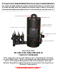
IT’S FINALLY HERE A HYDRONIC BUFFER TANK WITH THE PUMPS, CONTROLS AND VALVES ALL IN ONE. NO MORE HASSLES OF TRYING TO MOUNT EVERYTHING. ALL YOU HAVE TO DO IS PLUMB THE LINES, WIRE THE THERMOSTATS, AND HEAT PUMP, THEN FILL THE SYSTEM. THE NON PRESSURIZED TANK KEEPS AIR OUT OF YOUR SYSTEMS SO YOU DON’T HAVE TO.
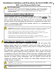
Installation Guidelines and Procedures for B & D MFG., INC. HSS Series Hydronic Buffer Tank ® SAFETY INSTRUCTIONS This safety alert symbol will be used in this manual to draw attention to safety related instructions. When used, the safety alert symbol means: ATTENTION! BECOME ALERT! YOUR SAFETY IS INVOLVED! FAILURE TO FOLLOW THESE INSTRUCTIONS MAY RESULT IN A SAFETY HAZARD. TANK PLACEMENT REQUIREMENTS A level location with 36" of clearance on the front of tank required.
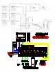
THERMOSTAT WIRING The HSS® can provide heating/cooling control and heating only control depending on the system requirements. Any terminal block located on the HSS® control board can be used for heating and/or cooling however the HO/HC jumper must be on HC to enable cooling control for its corresponding zone. (See schematic on page 7) Heating & Heating Cooling- Connect thermostat wire R to its corresponding pump zone on the HSS® Control R terminal.
PURGING HSS BUFFER TANK ® The HSS® Buffer Tank can have several loops or circuits and each one should be purged separately. The HSS Buffer Tank shall be filled with water prior to running any of the circulator pumps. Keep a water source nearby to fill the tank as necessary. As air is relieved from the system piping water will need to be added.
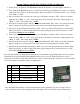
PROGRAMMING OF THE B&D TEMPERATURE CONTROLLER 1. Power needs to be applied to the HSS Buffer Tank, the Temperature controller display will turn on. 2. Press and hold the MODE button for 5 seconds and it will enter programming mode. After 2 seconds the temperature scale will show on the LCD display. By pressing the up or down button allows you to change from “FAR” or “CEN”. 3. Press mode button once and enter the control type. The display will show “TY1”.
DIAGNOSTICS Water runs out of the top of the HSS® Buffer Tank 1. Air in zones will cause water to over flow when pumps are shut off. 2. A water line leak above the height of the Buffer Tank could cause air to enter and allow the water to run out. 3. If the HSS® Buffer Tank was filled during the air conditioning season and then operating in the heating season, the water level can rise and overflow. 4.
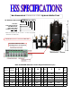
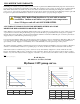
® Non-Pressurized STAINLESS STEEL Hydronic Buffer Tank GT Stainless Steel Tank HSS60-3-1-G-13 Tank Size Total Hydronic Circuits Total W/W Circuits B-B&G; G-Grundfos Voltage (1-115; 3-230) *Hydronic circuit ball valve 3/4”on 15/58, 1” on 26/99-3 speed pump. W /W Side 1-1/4” Ball Valve 1 1/4” FPT w/ Ball Valve Tank Water Level is 3” to 4” Down on Main Tank Control Board Electrical Data: 115V/Single Phase 15 amp Circuit HSS® GT BUFFER TANK Flow Center Physical Dimensions (in.
HSS® BUFFER TANK WARRANTY B & D Mfg., Inc. warrants for a period of three (3) years from date of purchase that all HSS® Buffer Tank pumps and circuit boards are free from defects in materials and workmanship. B & D Mfg., Inc. warrants for a period of five (5) years from date of purchase that all HSS® Buffer Tank, stainless steel tanks only, are free from defects in materials and workmanship. B & D Mfg., Inc.