Washer-Extractor SP Series Installation and Operation Manual October 14, 2014 Revision 3.
Contents 1 2 Important Instructions 2 1.1 Before Attempting Repairs . . . . . . . . . . . . . . . . . . . . . . . . . . . . . . . . . . 2 1.2 Parts Ordering Information . . . . . . . . . . . . . . . . . . . . . . . . . . . . . . . . . 3 1.2.1 Nameplate Location . . . . . . . . . . . . . . . . . . . . . . . . . . . . . . . . . 3 1.3 Key Symbols . . . . . . . . . . . . . . . . . . . . . . . . . . . . . . . . . . . . . . . . . . 3 1.4 Safety Information . . . . . . . . . . . . . . . . . . . .
4.2.7 5 Machiner Misuse . . . . . . . . . . . . . . . . . . . . . . . . . . . . . . . . . . . 17 4.3 Dimensional Clearances . . . . . . . . . . . . . . . . . . . . . . . . . . . . . . . . . . . 18 4.4 Machine Foundation . . . . . . . . . . . . . . . . . . . . . . . . . . . . . . . . . . . . . 18 4.4.1 Mounting Bolt Installation . . . . . . . . . . . . . . . . . . . . . . . . . . . . . . 19 4.4.2 Mounting Bolt Location . . . . . . . . . . . . . . . . . . . . . . . . . . . . . . . 27 4.
5.3.9 6 7 8 Halting a Program . . . . . . . . . . . . . . . . . . . . . . . . . . . . . . . . . . 45 5.3.10 Water Level Refresh . . . . . . . . . . . . . . . . . . . . . . . . . . . . . . . . . 45 5.3.11 Unbalance . . . . . . . . . . . . . . . . . . . . . . . . . . . . . . . . . . . . . . . 46 5.3.12 Power Failure . . . . . . . . . . . . . . . . . . . . . . . . . . . . . . . . . . . . . 46 5.3.13 End of Program . . . . . . . . . . . . . . . . . . . . . . . . . . . . . . . . . . . . 46 5.3.
Figure 1: SP Product Family 1
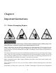
Chapter 1 Important Instructions 1.1 Before Attempting Repairs Moving parts can cause serious injury or death. Before attempting repairs, follow proper shutdown procedures and remove power before commencement of service. Safety is of primary concern with any maintenance or repair operation.
is available to answer any questions you may have about the operation and servicing of your machine. Please call with any questions or concerns about the operation of your machine. 1.2 Parts Ordering Information If you require literature or spare parts, please contact your local distributor. If a local distributor is unavailable, you may contact B&C Technologies directly at (850) 249-2222 for the name of your nearest parts dealer.
Figure 1.1: Serial Decal 1.5 Installation and Operational Safety Instructions 1. Read all instructions prior to operating this equipment. 2. Ensure that the equipment is properly grounded before applying power and operation commences. 3. Do not allow children to play in or around or operate this equipment. 4. Check the operation of all safety interlocks at the start of every shift. If the interlocks do not stop the equipment immediately, the machine must be removed from service.
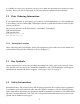
Figure 1.2: Key Symbols Figure 1.3: Key Symbols 10. Keep the interior and exterior of the machine clean of lint, dirt, dust and debris. 11. Always disconnect the electrical service from the machine before performing service.
12. This machine must be installed according to the installation instructions. All utility connections must comply with state and local codes and must be made by a licensed installer where required.
Chapter 2 Introduction The B&C SP Series is the professional freestanding washer-extractor series of machines from B&C Technologies. It is an open pocket washer-extractor with a large door opening for easy and quick loading and unloading. It has been developed for the on premise market, and is suitable for commercial laundries, hotel and other places where laundry might be processed The design allows for top performance at lowest possible operation cost and investment.
2.1 Customer Service For technical assistance: In the United States Phone: (850)-249-2222 FAX: (850) 249-2226 e-mail: techsupport@bandctech.com Web: www.bandctech.com 2.2 Replacement Parts In the event that literature or replacement parts are required, contact the local distributor of the equipment, or contact B&C Technologies at the above phone numbers/internet addresses. 2.3 Theory of Operation The B&C SP models use a single-speed motor to drive the cylinder via V-belts in all speeds.
oclock or 1-2 oclock positions. This mechanical action removes soil from the fabric. Furthermore, the lifters are perforated on the top so that water can cascade over the goods and wet them quickly. This reduces water consumption as water is picked up at the cylinders lowest point and lifted and splashed over the goods at the highest point as the cylinder rotates. A stainless steel door is provided for loading and unloading. A door lock system prevents operation of the machine when the door is open.
Chapter 3 General Specifications 10
MODEL Maximum Capacity Overall Dimensions A - Width B - Depth C - Height Wash Cylinder Information Cylinder Diameter Cylinder Depth Cylinder Volume Motor Size Cylinder Speeds (Programmable) Wash Distribution Intermediate Extract High Extract 1 High Extract 2 High Extract 3 Door Opening Door Opening Diameter Height to Bottom of Door Drain System Overflow Size Drain Outlet Size Number of Drains Steam Inlet Connection Size Water Inlet Connection Size Number of Inlets Chemical Supply System Dry Chemical Compart
MODEL Maximum Capacity Overall Dimensions A - Width B - Depth C - Height Wash Cylinder Information Cylinder Diameter Cylinder Depth Cylinder Volume Motor Size Cylinder Speeds (Programmable) Wash Distribution Intermediate Extract High Extract 1 High Extract 2 High Extract 3 Door Opening Door Opening Diameter Height to Bottom of Door Drain System Overflow Size Drain Outlet Size Number of Drains Steam Inlet Connection Size Water Inlet Connection Size Number of Inlets Chemical Supply System Dry Chemical Compart
Chapter 4 Installation 4.1 Receiving Inspection Upon receipt of the equipment, visually inspect for shipping damage and note any damage with the carrier before signing the shipping receipt, or advise the carrier of the damage as soon as it is noted. If damage is discovered, a written claim must be filed with the carrier as soon as possible. Note: Warranty is VOID unless the equipment is installed according to instructions. The installation must comply with the minimum requirements listed in this manual.
Before servicing any equipment, make certain it is disconnected from the electrical power source. Never allow operation of the machine when any safety device is malfunctioning. Never bypass safety devices. Never insert hands or objects into basket until it has completely stopped. Doing so could result in serious injury. 1. When the washer is energized electrically and in operation, the loading door must be locked in the closed position.
Never operate the machine with a bypassed or disconnected out-of-balance switch. Operating the machine with severe out-of-balance loads could result in personal injury and serious equipment damage. Do not place volatile or flammable fluids in any machine. Do not clean the machine with volatile or flammable fluids such as acetone, lacquer thinners, enamel reducers, carbon tetrachloride, gasoline, benzene, naphtha, etc. Doing so could result in serious personal injury and/or damage to the machine. 4.2.
Replace all panels that are removed to perform service and maintenance procedures. Do not operate the machine with missing guards or with broken or missing parts. Do not bypass any safety devices. 4.2.4 Machine Location 1. Foundation. The concrete floor must be of sufficient strength and thickness to handle the floor loads generated by the machine at high extract speeds. 2. Service/ Maintenance Space. Provide sufficient space to allow comfortable performance of service procedures and routine maintenance.
Always disconnect power and water supplies before a service technician performs any service procedure. Where applicable, steam and/or compressed air supplies should also be disconnected before service is performed. 4.2.6 Inverter Drive Machines equipped with AC drives require special attention with regard to the operating environment. 1. An especially dusty or linty environment will require more frequent cleaning of the AC drive cooling fan filter and of the AC drive itself. 2.
4.3 Dimensional Clearances When installing the washer-extractor, it is important to allow adequate clearance on all sides of the machine. When multiple machines are installed, it is important to allow for the specified minimum clearances between machines. The following table shows recommended minimum clearances for the various freestanding models. Note: The dimensions are approximate and subject to normal manufacturing tolerances.
For a successful installation, a smooth level surface, so that the entire base of the machine is supported and rests on the mounting surface, is absolutely requried. Note: Do not support the machine on only four points. Note: Freestanding washer-extractors do not require anchoring bolts unless specified by state or local codes. However it is always recommended that the machines be anchored. Special care must be taken when machines are installed on an upper floor.
Figure 4.
Figure 4.
Figure 4.
Figure 4.
Figure 4.
Figure 4.
Figure 4.
Figure 4.9: SP-185/195 Bolt Hole Layout 4.4.2 Mounting Bolt Location All B&C washer-extractors should be secured by the use of machinery anchor bolts. High strength machinery anchors should be embedded in 3500 psi (24000 N/m2) reinforced concrete. For detailed information regarding the machine anchor bolt, see the instructions included with the anchor bolts themselves. The information provided is just an example. Ensure that the concrete is fully cured before proceeding.
Figure 4.10: Typical Machinery Anchor Installation 1. Remove the wood skid by unscrewing the carriage bolts holding it to the bottom frame of the machine. 2. Carefully place the machine over the anchor bolts. Raise and level it 1/2 inch above the floor on four points, using spacers that can be removed. 3. Fill the spaces between the machine base and floor with machinery grout. Grout completely under all frame members. Remove front panel and rear panel to gain access to all frame members.
Figure 4.11: Typical Machinery Transportation Bracket Location 4.6 Drain Installation A drain system of adequate capacity is essential to the machine performance. Ideally the water should empty through a 4 inch vented pipe directly into a sump or floor drain. See figure 4.12 on 30. A flexible connection must be made to a vented drain system to prevent an airlock or siphon effect. If proper drain size is not available or practical, a surge tank is required.
Figure 4.12: Drain System Information This machine must be installed, adjusted, and serviced by a qualified electrical maintenance personnel familiar with the construction and operation of this type of machinery. They must also be familiar with the potential hazards involved. If this warning is not observed, personal injury or equipment damage resulting in voiding the warranty may result. 4.7 Electrical Installation The AC drive requires a clean power supply free from voltage spikes and surges.
If controlling the AC drive with a parameter unit, the machines computer and its safety features are bypassed. This could allow the basket to rotate at high speeds with the door open. When using a parameter unit to control the AC drive, a large sign should be placed on the front of the machine warning people of the imminent danger. Never touch terminals or components of the AC drive unless power is disconnected and the ”‘CHARGE”’ indicator LED is off.
Note: Wire sizes shown are for copper, THHN, 90 conductor per NEC article 310 (USA). The machine should be connected to an individual branch circuit not shared with lighting or other equipment. Because this is a vibrating machine, the use of SO cable or similar, with a twist-lock plug, to connect the machine to main power is recommended.
4.8 Water Connection Individual hot and cold plumbing lines with individual shut-off valves must be available to the machine. Hot water should be minimum of 160F (70C). If lower temperature water is used the machine can be equipped for steam heating to heat the wash solution to desired temperature. Best performance will be realized if water is provided at a pressure of 30-85 psi (2-7 Bar). Although the machine will function properly at lower pressures, increased fill times will occur.
Table 4.4: SP-40 thru SP-65 Water Requirements Connection Size US Metric 3/4” DN 19 Water Line Pressure PSI Bar 30-75 2-5 Max Temp F C 200 93 Flow Rate (@45PSI/3Bar) gal/min liter/min 11 40 Minimum Supply Line Size US Metric 3/4 DN 19 Max Operating Pressure US Metric 125 PSI 8 Bar Table 4.
STEAM INLET and CONSUMPTION: UNITS Steam inlet size DN in Required steam to heat bath 10F (5.55C)LOW kg lbs Required steam to heat bath 10F (5.55C)HIGH kg lbs Average Steam consumption per cycle kg lbs SP-40/45 13 1/2 1.2 2.4 1.4 3.1 23 50.6 STEAM INLET and CONSUMPTION: UNITS SP-60/65/75 Steam inlet size DN in 13 1/2 Required steam to heat bath 10F (5.55C)LOW kg lbs 1.5 3.2 Required steam to heat bath 10F (5.55C)HIGH kg lbs 1.
4.10 Compressed Air Connection SP-130/135, SP-155/165, SP-185/195 only SP-110 and smaller do not require compressed air. Best performance will be realized if air is provided at a pressure of 80-100psi (5.4-6.7 bar). SP-130 and larger machines will experience door seal and drain failure if compressed air service is interrupted. Ensure the provided air is filtered and dry. Wet and/or dirty air will cause rapid deterioration of internal components and void your warranty on these parts.
Undiluted chemicals dripping can damage the machine. Therefore, all chemical supply dispenser pumps should be mounted below the washers injection point. All dispenser tubing should also run below the injection point. Loops do not prevent drips if these instructions are not followed. Failure to follow these instructions could damage the machine and void the warranty. Figure 4.16: External Chemical Supply Connection Detail 4.11.
2. Install the supplied chemical nipple, using teflon tape. 3. Insert tubes onto the nipples, using small hose clamps or wire ties to prevent the hose from slipping off. The chemical flush water valve (relay 12) should be used with each chemical signal (see the EL6 programming manual for details). For the poly supply box, you must drill the nipples prior to use (max 1/4 bit). A NPT connection is also provided for flushing systems. The chemical flush valve is not necessary. See figure 4.18 on page 39. 4.11.
Figure 4.17: Stainless Steel Vacuum Breaker / Supply Box Figure 4.18: Poly Vacuum Breaker / Supply Box (a) Attempt to start the machine with the door open. The machine should not start with the door open. (b) Close the door without locking it and attempt to start the machine. The washer should not start with the door unlocked. (c) Close and lock the door and start a cycle. Attempt to open the door while the cycle is in progress. The door should not open.
Attempting to obtain power from the machine terminals may damage the machine circuit and/or the chemical injection system. Consult the chemical injection supply system instructions for operational details. Figure 4.19: External Chemical Supply Terminal Block Detail 7. For testing, select program 30 by pressing key 3 and key 0 on the keypad. Then press ENTER followed by the START key. Run the complete program, checking operation of water inlet valves, drain, and extract functions.
Chapter 5 Operation 5.1 Door Lock Operation The lock system uses a ”‘push-to-open / push-to-close”’ style mechanism which differentiates it from any other door lock in the industry. This design was developed as a result of analyzing the shortcomings of other door lock mechanisms on the market. It hence has many fundamental safety and mechanical advantages. 5.1.1 Opening and Closing the Door SP-110 and smaller To open the door the machine must not be running a wash program – ”‘Program n.
5.1.2 Periodic Maintenance • The door should be tested every day for safe operation by trying to start a program with the door open. If the machine will begin operation in this state it should immediately be removed from service, locked out, and a qualified service technician called to repair it. • If the door lock is malfunctioning in any way, the machine should immediately be removed from service, locked out, and a qualified service technician called to repair it.
Dry Weight Capacity Model Capacity SP-40 40 lbs 18 kg SP-45 45 lbs 21 kg SP-50 50 lbs 23 kg SP-60 60 lbs 27 kg SP-65 65 lbs 30 kg SP-100 100 lbs 45 kg SP-110 110 lsb 50 kg SP-130 130 lbs 59 kg SP-135 135 lbs 61 kg SP-155 155 lbs 71 kg SP-165 165 lbs 75 kg SP-185 185 lbs 84 kg SP-195 195 lbs 89 kg Table 5.1: Proper Load Sizing 5.3 Wash Program Execution After power is applied to the machine, and the internal diagnostics are complete, the machine is ready for a program to be chosen.
3 seconds, the required value to advance. If INC or DEC is pressed, you can temporarily modify the value for the current step. Pressing TEMP allows you to see the current temperature of the water. Pressing the TIME key shows the watch dog timer (WDT) value for the current step. 5.3.2 End Step Condition: Temperature If the end condition of the segment is a temperature, the display will show: WASH3 TEMP=35C where 35C is the actual temperature of the wash solution.
5.3.5 Partial Program A program can be started from the beginning, or at any subsequent cycle. After selecting the program you wish to execute, the display will show: PRWH1 EXECUT.? Instead of pressing START to execute the program, press the ADVANCE key. The cycles within the program will be displayed incrementally. Choose the point at which you would like to begin, and press the START key. The machine will begin operation from this point. 5.3.
5.3.11 Unbalance If the load is excessively out of balance, the spin routine will stop and a redistribution of the goods will take place. If three consecutive out of balances occur, the control will end the current program. After the first unbalance, the balance indicator will light on the EL6 control panel and remain illuminated until a new program is started. The balance indicator light does not necessarily indicate a problem, but that one or more retries was required. The FM7 has no indicator. 5.3.
Indicates the programmed temperature was not reached within the allotted time. The most common cause is a malfunctioning auxiliary heating system. A short WDT time and very cold water can also cause this problem. Pressing the START key will cancel the alarm and allow the program to continue. WDT LEVEL EXP eached within the allotted time.
MAINTENANCE The message appears at the start of a program, and is repeated at the beginning of each wash program until reset (see function 217 in the EL6/FM7 Programming and Operation Manual for full details). Before resetting the alarm, PERFORM ROUTINE MAINTENANCE AS OUTLINED ELSEWHERE IN THIS MANUAL. For further information regarding access functions and programming, see the EL6/FM7 Computer Programming and Operating Instructions manual, included with the machine or from the B&C Technologies website: www.
Chapter 6 Maintenance Routine maintenance maximizes operating efficiency and minimizes downtime. The maintenance procedures described below will prolong the life of the machine and help prevent accidents. Daily, weekly, monthly, and quarterly checklist are provided at the end of this section. Laminate the checklists to preserve them for repeated copying. Operators and technicians are encouraged to add checks specific to their machines particular application.
(b) Close the door without locking it and attempt to start the machine. The machine should not start with the door open. (c) Close and lock the door and start a cycle. Attempt to open the door while the cycle is in progress. The door should not open. If manual latch is moved out of position the machine should stop. If the door lock and interlock are not functioning properly, call a service technician. 6.1.2 End of Day 1. Clean the door gasket of residual detergent and foreign matters. 2.
1. Each month or after every 200 hours of operation, lubricate bearing and seals. See instructions on the machine. (a) Use a premium grade lithium complex grease. Never mix two types of grease. (b) Pump the grease gun slowly, permitting only the following number of strokes: (a) Bearing grease fitting, 2 strokes (b) Seal grease fitting, 1 stroke. Do not pump the grease gun if grease comes out of the bearing housing. This can result in over lubrication, causing damage to bearings and seals. 2.
Figure 6.1: Proper Pulley Alignment Figure 6.2: Belt Tensioning Bolt 1. Tighten door hinges and fasteners, if necessary. 2. Tighten anchor bolts, if necessary. 3. Check all painted surfaces for bare metal (matching paint is available from the manufacturer.) (a) If bare metal is showing, paint with primer or solvent-based paint. (b) If rust appears, remove it with sand paper or chemical means. Then paint with primer or solvent-based paint. 4. Clean steam filter, where applicable. See figure 6.3. 5.
Table 6.1: Belt Tension Guide Model SP-40/45 SP-60/65/75 SP-100/110 SP-130/135 SP-155/165 SP-185/195 in 0.24 6.1 0.29 7.4 0.33 8.4 0.3 7.6 0.29 7.4 0.52 13.2 lb 2.4 4.3 5.3 4.8 5.4 7.7 1.1 2 2.4 2.2 2.5 3.5 (b) Unscrew inlet hose and remove filter screen. (c) Clean with compressed air and reinstall. Replace if worn or damage. 8. Tighten motor mounting bolts and bearing housing bolts, if necessary. 9. Use compressed air to clean lint from motor. 10. Clean external water and steam filters Figure 6.
2. Contact with dissimilar metal should be avoided whenever possible. This will help prevent galvanic corrosion when salty or acidic solutions are present. 3. Salty or acidic solutions should not be allowed to evaporate and dry on stainless steel. They may cause corrosion. Ensure that the stainless steel is wiped clean of acidic solution residues. 4. Deposits that adhere to the stainless steel should be removed, especially from crevices and corners.
Chapter 7 Service & Parts 7.1 Service Service must be performed by a qualified trained technician, service agency, or gas supplier. If service is required, contact the distributor from whom the equipment was purchased. If the distributor cannot be contacted or is unknown, contact B&C Technologies for a distributor in your area. For technical assistance in the United States, contact B&C Technologies: (850) 249-2222 Phone (850) 249-2226 FAX parts@bandctech.com www.bandctech.
Chapter 8 Decommisioning In the event that the machine must be decommissioned, follow these steps: 1. Clean interior of machine, both basket and shell. 2. Disconnect electrical power. (a) Shut of main power supply at the breaker box or main control panel. (b) Do not attempt to disconnect power supply wires from power supply. Have a qualified electrician disconnect power to machine at its source. 3. Disconnect gas/steam supply. 4. Disconnect exhaust system. 5. Remove the machine from its foundation pad.