
Owner manual


particles out of the solenoid valves. Hang the hoses in a large loop. Do not allow the hoses to
kink. The water connections to the machine should be supplied by a hot and cold water line of
least the sizes shown in table 5.4 on page 23. Refer to table 5.5 and 5.6 on page 23 for details on
individual machine requirements.
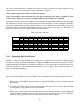
Table 5.4: Water Connection Detail
# OF MACHINES SUPPLY LINE PIPE SIZES
SI-110 SI-135 SI-200 SI-275
DN Inch DN Inch DN Inch DN Inch
1 25 1 32 1-1/4 32 1-1/4 40 1-1/2
2 25 1 32 1-1/4 32 1-1/4 40 1-1/2
3 40 1-1/2 50 2 50 2 50 2
4 40 1-1/2 50 2 50 2 50 2
5 50 2 63 2-1/2 63 2-1/2 63 2-1/2
6 50 2 63 2-1/2 63 2-1/2 63 2-1/2
To avoid eventual water hammer in the water line, suitable devices to reduce the water hammer
should be installed.
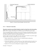
Table 5.5: SI-110 Water Requirements
Water Flow Rate Minimum Supply Max Operating
Connection Size Line Pressure Max Temp (@45PSI/3Bar) Line Size Pressure
US Metric PSI Bar F C gal/min liter/min US Metric US Metric
1” DN 25 30-75 2-5 200 93 30 113 1-1/4 DN 32 125 PSI 8 Bar
Table 5.6: SI-135 / SI-200 / SI-275 / SI-300 Water Requirements
Water Flow Rate Minimum Supply Max Operating
Connection Size Line Pressure Max Temp (@45PSI/3Bar) Line Size Pressure
US Metric PSI Bar F C gal/min liter/min US Metric US Metric
1-1/4” DN 32 30-75 2-5 200 93 37 140 1-1/2 DN 38 125 PSI 8 Bar
5.9 Steam Connection
For machines equipped with optional steam heat, install piping in accordance with approved com-
mercial steam practices. Steam requirements are shown in the table 5.7 on page 24. Failure to
install a steam filter/trap may void the warranty.
23