
Owner manual


For a successful installation, a smooth level surface, so that the entire base of the machine is sup-
ported and rests on the mounting surface, is absolutely requried.
Note: Do not support the machine on only four points.
Note: Freestanding washer-extractors do not require anchoring bolts unless specified by state
or local codes. However it is always recommended that the machines be anchored.
Special care must be taken when machines are installed on an upper floor. Make sure that the floors
are designed to carry the static and dynamic loads of the machines. Further vibrations should be
taken into consideration so that the machine does not create vibrations in the building. Static and
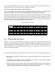
dynamic loads on the floor or foundation are shown in the figure 5.2 on page 18. This table can
be used as reference when designing floors and foundations.
Table 5.2: Floor Load Data
Static floor load Static pressure Dynamic floor load Max dynamic load Dynamic pressure
kN lbs kN/m2 lbs-ft2 kN lbs kN lbs kN/m2 lbs-ft2
SI-110 15 3300 5.7 117 1.5 330 1.5 330 0.57 11.7
SI-110 TILT 17 3900 6.5 138.5 1.5 330 1.5 330 0.57 11.7
SI-135 22.3 4900 7.4 152 1.5 330 1.5 330 0.5 10.25
SI-135 TILT 24.9 5600 8.3 173.9 1.5 330 1.5 330 0.5 10.25
SI-200 26.8 5900 7.13 149 2.45 540 2.45 540 0.88 18.3
SI-200 TILT 30.25 6800 7.13 149 2.45 540 2.45 540 0.88 18.3
SI-275 47.7 10500 11.96 248 4.09 900 4.09 900 1.04 21.3
SI-275 TILT 51.3 11300 13.05 267 4.09 900 4.09 900 1.04 21.3
5.4.1 Mounting Bolt Installation
All B&C washer-extractors should be secured by the use of machinery anchor bolts. High strength
machinery anchors should be embedded in 3500 psi (24000 N/m2) reinforced concrete. For de-
tailed information regarding the machine anchor bolt, see the instructions included with the an-
chor bolts themselves. The information provided is just an example. Ensure that the concrete is
fully cured before proceeding.
Place the machine adjacent to the foundation. Do not attempt to move it by pushing on the sides.
1. Remove the wood skid by unscrewing the carriage bolts holding it to the bottom frame of
the machine.
2. Carefully place the machine over the anchor bolts. Raise and level it 1/2 inch above the floor
on four points, using spacers that can be removed.
3. Fill the spaces between the machine base and floor with machinery grout. Grout completely
under all frame members. Remove front panel and rear panel to gain access to all frame
members. Force grout under the machine base until all voids are filled.
18