
Owner manual


5.3 Dimensional Clearances
When installing the washer-extractor, it is important to allow adequate clearance on all sides of the
machine. When multiple machines are installed, it is important to allow for the specified minimum
clearances between machines. Figures 5.1 and 5.1 show recommended minimum clearances for
the various freestanding models.
Note: The dimensions are approximate and subject to normal manufacturing tolerances. If
exact dimensions are required for construction purposes, request certified drawings from the
factory. We reserve the right to make changes at any time without notice.
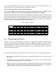
Figure 5.1: Minimum Service Clearances
Table 5.1: Minimum Service Clearnances
UNITS UNITS SI Series SI Series Tilt
Metric US
(A) Minimum rear clearance mm in 760 30 760 30
(B) Minimum clearance between machine and wall mm in 455 18 455 18
(C) Minimum clearance between machines mm in 455 18 455 18
(D) Minimum front clearance mm in 850 33 1220 48
5.4 Machine Foundation
Thoroughness of details must be stressed with all foundation work to insure a stable unit installa-
tion, eliminating possibilities of excessive vibrations during extraction.
17