Washer-Extractor HP Series Installation and Operation Manual B&C Technologies Accurate Technologies Panama City, FL (850) 249-2222 (850) 249-2226 FAX www.bandctech.com Samutprakarn, Thailand +66 (0) 2740-5511 +66 (0) 2740-5522 FAX www.accuratethai.com Revision1.
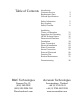
Table of Contents Introduction Customer Service Replacement Parts General Specifications 3 3 4 Safety Information Key Symbols Safety Checklist 5 5 6 Installation Theory of Operation Inspection and Uncrating HP-60 Technical Specs Dimensional Clearance Foundation Drain Connection Electrical Installation Water Connection Steam Connection External Chemicals Function Test Routine Maintenance 11 13 16 17 18 22 23 24 25 26 29 31 Decomissioning 36 B&C Technologies Accurate Technologies Panama City, FL (8
Introduction HP Series Washer-Extractors The B&C HP line is the professional fixed mount washer-extractor series of machines from B&C Technologies. It is an open pocket washer-extractor with a large door opening for easy and quick loading and unloading. It has been developed for the on premise market, and is suitable for commercial laundries, hotel and other places where laundry might be processed The design allows for top performance at lowest possible operation cost and investment.
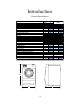
Introduction General Specifications MODEL Units Metric US HP-60 OVERALL DIMENSIONS: A - Width mm in 880 B - Height mm in 1650 C - Depth mm in 1190 WEIGHT AND SHIPPING INFORMATION: Net Weight kg lbs 660 Domestic shipping weight kg lbs 720 CYLINDER INFORMATION: Diameter mm in 790 Depth mm in 560 Volume liters cu ft 274 Capacity, 1:10 fill ratio kg lbs 27.
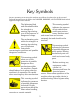
Key Symbols Anyone operating or servicing this machine must follow the safety rules in this manual. Particular attention must be paid to the DANGER, WARNING, and CAUTION blocks which appear throughout the manual The lightening flash and arrowhead within the triangle is a warning sign alerting you of the presence of dangerous voltage. This warning symbol indicates the presence of hot surfaces that could cause serious burns. Stainless steel and steam lines can become extremely hot and should not be touched.
Introduction Safety Checklist Before Initial start up of a B&C washer extractor perform the following safety check: call a qualified service technician. If additional information is required, contact your local distributor or call the manufacturer of the machine. A. Make sure all electrical and plumbing connections have been made in accordance with applicable codes and regulations. Before servicing any equipment, make certain it is disconnected from the electrical power source.
Introduction Safety Checklist To provide personal safety and keep the machine in proper working order, follow all maintenance and safety procedures presented in this manual. If questions regarding safety arise. Contact the factory immediately. 3.2 Excessively high water level is evident. 3.3 Machine is not connected to a properly grounded circuit. Use factory authorized spare parts to avoid safety hazards. Do not bypass any safety devices in the machine.
Introduction Safety Checklist Safe Operation Environment where floor space is shared with equipment sensitive to radio frequency emissions. All machines that are shipped to CE countries are equipped with this filter and comply with the EMI regulations. Safe operation requires an appropriate operating environment for both the operator and the machine. If questions regarding safety arise, contact the factory. Environmental Conditions 5. Elevation.
Introduction Safety Checklist iinstall the supplied steam filter may void the warranty. 2. Service/ Maintenance Space. Provide sufficient space to allow comfortable performance of service procedures and routine maintenance. This is especially important in connection with machines equipped with AC inverter drives. Consult installation instructions for specific details. 3. Drainage System.
Introduction Safety Checklist AC Inverter Drive Machines equipped with AC drives require special attention with regard to the operating environment. 1. Never wash petroleum-soaked rags in the machine. This could result in an explosion 2. Never wash machine parts or automotive parts in the machine. This could result in serious damage to the basket. 1. An especially dusty or linty environment will require more frequent cleaning of the AC drive cooling fan filter and of the AC drive itself. 3.
Installation Theory of Operation The B&C HP models use a single-speed motor to drive the cylinder via V-belts in all speeds. The cylinder is supported by two spherical roller bearings located in a bearing housing made of cast iron. The steam, if installed is injected in the bottom of the shell via a steam injector. The steam is controlled by a steam valve that is programmed by the micro computer.
Installation Theory of Operation front of the machine and is accessed by opening the cover door. Supplies, both liquid and powder; may be added by pulling the dispenser cups out and placing the appropriate supply in each. Supplies are flushed into the machine at the proper time in the cycle, controlled by the micro computer. Holes are provided at the rear of the machine for connection to an external, central liquid supply unit.
Installation Inspection and Uncrating Delivery inspection NOTE! Keep the manuals, installation instructions and the wiring diagrams which accompany the machine in a safe place for ready reference. They have been included with the machine at no charge. Additional copies are available at a nominal charge. Upon delivery, visually inspect crate, protective cover, and unit for any visible shipping damage.
Installation HP-60 Technical Specifications MODEL Units Metric US CAPACITY: Loading factor 1:10 1:12 1:13 OVERALL DIMENSIONS: Width Height Depth WEIGHT AND SHIPPING INFORMATION: Net Weight Domestic shipping weight CYLINDER INFORMATION: Diameter Depth Volume Perforation size Perforation open area CYLINDER SPEEDS (Programmable): Wash Distribution Intermediate extraction High extract 1 High extract 2 High extract 3 14 HP-60 kg kg kg lbs lbs lbs 27.4 22.8 21.1 60 50.2 46.
Installation HP-60 Technical Specifications MODEL DOOR OPENING AND HEIGHT: Diameter Height of door bottom above floor DRIVE INFORMATION: Number of motors Size of motor WATER INLETS and CONSUMPTION: Hot water size Cold water size Additional water Inlet Average HOT water consumption/ cycle Average COLD water consumption/cycle DRAIN OUTLETS AND CAPACITY: Number of drains standard Number of drains optional (water re-use) Drain size Drain capacity STEAM INLET and CONSUMPTION: Steam inlet size Required steam to h
Installation Dimensional Clearances Note When installing the washer-extractor, it is important to allow adequate clearance on all sides of the machine. When multiple machines are installed, it is important to allow for the specified minimum clearances between machines. The following table shows recommended minimum clearances for the various freestanding models.
Installation Machine Foundation A proper foundation is an absolute necessity when installing a fixed mount washer extractor. Do not neglect details when doing foundation work. These details will ensure a stable installation, reducing the possibility of excess vibration at high speeds. level floor of sufficient strength and that the recommended clearances for inspection and maintenance are provided.
Installation Foundation Bolt Location 5 each side Typical Grouting Pattern Front of Machine 18
Installation Mounting Bolt Installation All B&C washer-extractors must be secured by the use of machinery anchor bolts. High strength machinery anchors should be embedded in 3500 psi (24000 N/m2) reinforced concrete. See Figure. For detailed information regarding the machine anchor bolt, see the instructions included with the anchor bolts themselves. The following information is just an example.
Installation Mounting Bolt Installation FRONT OF MACHINE 31.50 [800.00] 35.43 [900.00] FRONT OF MACHINE 20.87 [530.00] 16.93 [430.00] 20.87 [530.00] 16.93 [430.00] 35.43 [900.00] 31.50 [800.00] 44.82 [1138.46] 23.23 [590] 39.14 [994.03] 28.74 [730] 31.89 [810] 42.37 [1076.15] 31.22 [793] 36.10 [917] 47.67 [1210.83] 38.11 [968] HP-60 HP-60 Mounting Bolt Installation The HP-60 requires the use of 3/4-10 x 8” bolts.
Installation Drain Connection A drain system of adequate capacity is essential to the machine performance. Ideally the water should empty through a 4 inch vented pipe directly into a sump or floor drain. See figure. installation procedures is attempted, the customer or installer should contact the manufacturer. Increasing the drain hose length, installing elbows, or causing bends will decrease drain flow rate and increase drain time, impairing machine performance.
Installation Electrical Installation The AC drive requires a clean power supply free from voltage spikes and surges. A voltage monitor should be used to check incoming power. The customer’ s local power company may provide such a monitor. If input voltage measures above 230V for a 200 V drive or above 440V for a 400V drive, either ask the power company if their representative can lower the voltage or install a step-down transformer kit available from the manufacturer.
Installation Electrical Installation 200-240V 380-480V Machine Max Amps Breaker Wire Size Max Amps Breaker Wire Size HP-60, 3PH 8 15 14ga / 2.5mm 4 15 14ga / 2.5mm HP-60, 1PH 13.6 15 14ga / 2.5mm larger for runs greater than 100 feet (30m). Note: For single phase (1N) operation, connect input power to L1 and L2, leaving the L3 terminal open.
Installation Water Connection Individual hot and cold plumbing lines with individual shut-off valves must be available to the machine. Hot water should be minimum of 160F (70C). If lower temperature water is used the machine should be equipped for steam heating to heat the wash solution to desired temperature. Best performance will be realized if water is provided at a pressure of 30-85 psi (2-7 Bar). Although the machine will function properly at lower pressures, increased fill times will occur.
Installation Steam Connection Never touch internal or external steam pipes, connections, or components. These surfaces can be extremely hot and will cause severe burns. The steam must be turned off and the pipe, connections, and components allowed to cool before the pipe can be touched in the table below. Failure to install the supplied steam filter may void the warranty. For machines equipped with optional steam heat, install piping in accordance with approved commercial steam practices.
Installation External Chemical Supplies Wear Eye and hand protection when handling chemicals. Always avoid direct contact with raw chemicals. Read the manufacturer’s directions for accidental contact before handling chemicals. Ensure that an eye-rinse facility and an emergency shower are within easy reach. Check at regular intervals for chemical leaks. The following procedures must be observed when connecting any chemical injector to the washer-extractor.
Installation External Chemical Supplies The supply compartment on the B&C HP models is located on the front of the machine. Supply cups can be accessed by opening the dispenser lid. The supply cups can be removed and filled as desired. Supply compartments are numbered 1,2,3,4 and 5 from the left of the machine to the right for the optional 5 cup system.. External supply connections for the B&C HP washer-extractors are located on rear of the machine at the vacuum breaker.
Installation Electrical Connections Connection terminals are located in the rear control box for output signals to the chemicals injection supply pump. Do not attempt to increase fuse rating as this cause damage to the washer-extractor circuitry. Terminals SUPPLY 1 through SUPPLY 8 provide signals for external chemical supply pumps. The signal is a maximum 1 amp at 24V 50/60Hz. Any injection system pump, which requires 24-220V AC must be powered by a separate external power source.
Installation Control Function Test The machine should be cleaned after the installation is complete. A function test should then be executed on the unloaded machine as follows: 1. 2. door unlocked. c. Check the proper supply for such characteristics as correct voltage, phase, and cycles to be certain they are correct for the machine. If the door lock and interlock are not functioning properly, call a service technician. Open manual shut-off water valves to the machine. 3. Press Emergency Stop button.
Operation Door Lock Operation The lock system uses a "push-to-open / push-to-close" style mechanism which differentiates it from any other door lock in the industry. This design was developed as a result of analyzing the shortcomings of other door lock mechanisms on the market. It hence has many fundamental safety & mechanical advantages. Periodic Maintenance >The door should be tested every day for safe operation by trying to start a program with the door open.
Maintenance Routine Maintenance Routine maintenance maximizes operating efficiency and minimizes downtime. The maintenance procedures described below will prolong the life of the machine and help prevent accidents. Daily, weekly, monthly, and quarterly checklist are provided at the end of this section. Laminate the checklists to preserve them for repeated copying. Operators and technicians are encouraged to add checks specific to their machine’s particular application.
Maintenance Routine Maintenance NOTE: Leave loading door open at end of each complete cycle to allow moisture to evaporate. Unload the machine promptly after each completed cycle to prevent moisture build up. #2 grease. Never mix two types of grease, such as petroleum and silicone. b. Pump the grease gun slowly, permitting only the following number of strokes: 1. Bearing grease fitting, 2 strokes 2. Seal grease fitting, 1 stroke. Weekly 1. Check the machine for leaks. a.
Maintenance Routine Maintenance b. After disconnecting power to the machine and removing all panels necessary for access to the drive belts, use the following method to verify that the V-belts are properly tensioned. Belt tensioning is straightforward, and accomplished by loosening the tension adjusting bolts and adjusting the belts to the proper tension. Then the bolts should be tightened. See figure. c. Verify that V-belts are properly aligned by checking pulley alignment.
Maintenance Routine Maintenance Quarterly 5. Remove back panel and check overflow hose and drain hose for leaks. NOTE: Disconnect power to the machine before performing the quarterly maintenance procedures. 6. Unlock the hinged lid and check the supply dispenser hoses and hose connections. 1. Tighten door hinges and fasteners, if necessary. 7. Clean inlet hose filter screen: a. Turn water off and allow valve to cool, if necessary. 2. Tighten anchor bolts, if necessary. 3.
Maintenance Routine Maintenance Care of stainless steel when possible. Maintain the natural beauty of stainless steel and prolong its service life by following these steps. 6. Discolorations or heat tint from overheating may be removed by scouring with powder or by employing special chemical solutions. 1. Ordinary deposits if dirt and grease can be removed with detergent and water. The metal should be thoroughly rinsed and dried after washing.
Decomissioning Decommissioning supply to the machine. d. Allow time for residual water in the machine to drain. Then disconnect drain hoses from the machine. e. Disconnect necessary plumbing on the re-circulation system, if applicable. In the event that the machine must be decommissioned, follow the following steps: 1. Remove the chemical injection supply system, if applicable. a.