Washer-Extractor HI Series Installation and Operation Manual B&C Technologies Panama City, FL (850) 249-2222 (850) 249-2226 FAX www.bandctech.com Revision 1.
Table of Contents Introduction Customer Service Replacement Parts General Specifications 4 4 5 Safety Information Key Symbols Safety Checklist 5 7 8 Installation Theory of Operation Inspection and Uncrating Dimensional Clearance Foundation Drain Connection Electrical Installation Water Connection Steam Connection External Chemicals Function Test Operation Routine Maintenance 13 15 16 17 19 20 22 23 25 27 28 33 Decomissioning 38 B&C Technologies Panama City, FL (850) 249-2222 (850) 249-2226 FAX www.
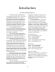
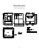
Introduction HI Series Washer-Extractors The HI line is the industrial fixed mount washer-extractor series of machines from B&C Technologies. It is an open pocket washer-extractor with a large door opening for easy and quick loading and unloading.
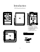
Introduction HI-85 General Specifications 6 4 4 152 100 100 58.3 1482 52.4 1332 46.5 1182 62.6 1590 7.7 196 7.25 184 35.6 905 62.6 1590 43.7 1110 54.5 1385 3X 15.2 386 4 101 6.1 155 4 101 A - AIR VENT B - HOT WATER, 1 INCH NPT C - COLD WATER, 1 INCH NPT D - STEAM INLET, 3/4 INCH NPT E - ELECTRICAL INLET F - CHEMICAL SIGNAL G - DRAIN OUTLET, 3 INCH 1 25 15.75 400 51.6 1310 15.75 400 13A 7A 6.1 155 14@0.67 (17) Floor Detail 61.
Introduction HI-125 General Specifications 1.
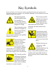
Key Symbols Anyone operating or servicing this machine must follow the safety rules in this manual. Particular attention must be paid to the DANGER, WARNING, and CAUTION blocks which appear throughout the manual The lightening flash and arrowhead within the triangle is a warning sign alerting you of the presence of dangerous voltage. This warning symbol indicates the presence of hot surfaces that could cause serious burns. Stainless steel and steam lines can become extremely hot and should not be touched.
Introduction Safety Checklist Before Initial start up of a B&C HI Series washer extractor perform the following safety check: operation,. Consult the service manual, or call a qualified service technician. If additional information is required, contact your local distributor or call the manufacturer of the machine. A. Make sure all electrical and plumbing connections have been made in accordance with applicable codes and regulations.
Introduction Safety Checklist To provide personal safety and keep the machine in proper working order, follow all maintenance and safety procedures presented in this manual. If questions regarding safety arise. Contact the factory immediately. 3.2 Excessively high water level is evident. 3.3 Machine is not connected to a properly grounded circuit. Use factory authorized spare parts to avoid safety hazards. Do not bypass any safety devices in the machine.
Introduction Safety Checklist Safe Operation Environment where floor space is shared with equipment sensitive to radio frequency emissions. All machines that are shipped to CE countries are equipped with this filter and comply with the EMI regulations. Safe operation requires an appropriate operating environment for both the operator and the machine. If questions regarding safety arise, contact the factory. Environmental Conditions 5. Elevation.
Introduction Safety Checklist iinstall the supplied steam filter may void the warranty. 2. Service/ Maintenance Space. Provide sufficient space to allow comfortable performance of service procedures and routine maintenance. This is especially important in connection with machines equipped with AC inverter drives. Consult installation instructions for specific details. 3. Compressed Air.
Introduction Safety Checklist malfunctions. procedures and routine preventive maintenance is especially important for machines equipped with AC drives. Always disconnect power and water supplies before a service technician performs any service procedure. Where applicable, steam and/or compressed air supplies should also be disconnected before service is performed Misuse Even though this machine is an atmospheric vessel, never use it for any purpose other than washing fabrics. AC Inverter Drive 1.
Installation Theory of Operation The B&C HI model uses a single-speed motor to drive the cylinder via V-belts in all speeds. The cylinder is supported by two spherical roller bearings located in split pillow block housings made of cast steel. bottom of the shell via a steam injector. The steam is controlled by a steam valve that is programmed by the EL6. The cylinder is perforated, allowing water to pass through and drain from within during drain and extract steps.
Installation Theory of Operation unlatching the cover door. Supplies, both liquid and powder; may be added by pulling the dispenser cups out and placing the appropriate supply in each. Supplies are flushed into the machine at the proper time in the cycle, controlled by the EL6. Holes are provided in the top of the supply dispenser (HI-125) or at the rear of the machine (HI-85) for connection to an external, central liquid supply unit.
Installation Inspection and Uncrating Delivery inspection NOTE! Keep the manuals, installation instructions and the wiring diagrams which accompany the machine in a safe place for ready reference. They have been included with the machine at no charge. Additional copies are available at a nominal charge. Upon delivery, visually inspect crate, protective cover, and unit for any visible shipping damage.
Installation Dimensional Clearances Note When installing the washer-extractor, it is important to allow adequate clearance on all sides of the machine. When multiple machines are installed, it is important to allow for the specified minimum clearances between machines. The following table shows recommended minimum clearances for the various freestanding models.
Installation Machine Foundation All B&C washer-extractors must be secured by the use of machinery anchor bolts. High strength machinery anchors should be embedded in 3500 psi (24000 N/m2) reinforced concrete. See Figure. For detailed information regarding the machine anchor bolt, see the instructions included with the anchor bolts themselves. The following information is just an example.
Installation Machine Foundation 4 101 3X 15.2 386 6.1 155 4 101 15.75 400 51.6 1310 15.75 400 1 25 6.1 155 14@0.67 (17) 61.4 1560 HI-125 HI-85 HI-125 Static floor load kN lbs 7.56 1700 19.53 4390 HI-85 Static pressure kN/m2 lbs-ft2 5.01 104.64 10.64 222.22 Dynamic floor load Dynamic pressure Dynamic Frequency kN lbs kN/m2 lbs-ft2 Hz 17.39 3910 11.52 240.6 9.65 25.58 5750 13.93 290.93 8 Mounting Bolt Installation The HI Series uses 5/8-11 x 8” bolts.
Installation Drain Connection A drain system of adequate capacity is essential to the machine performance. Ideally the water should empty through a 3 inch vented pipe directly into a sump or floor drain. See figure. Before any deviation from specified installation procedures is attempted, the customer or installer should contact the manufacturer. Increasing the drain hose length, installing elbows, or causing bends will decrease drain flow rate and increase drain time, impairing machine performance.
Installation Electrical Installation The AC drive requires a clean power supply free from voltage spikes and surges. A voltage monitor should be used to check incoming power. The customer’ s local power company may provide such a monitor. If input voltage measures above 240V for a 200 V drive or above 480V for a 400V drive, either ask the power company if their representative can lower the voltage or install a bucking transformer kit available from the manufacturer.
Installation Electrical Installation 200-240V 380-480V Machine Max Amps Breaker Wire Size Max Amps Breaker Wire Size HI-85 21 30 10ga / 4mm 11 15 10ga / 4mm HI-125 32 40 8ga / 10mm 16 20 10ga / 4mm Use wire sizes indicated in the chart for runs up to 50 feet (15m). Use next larger size for runs of 50 to 100 feet (15-30m). Use 2 sizes larger for runs greater than 100 feet (30m).
Installation Water Connection Individual hot and cold plumbing lines with individual shut-off valves must be available to the machine. Hot water should be minimum of 160F (70C). If lower temperature water is used the machine should be equipped for steam heating to heat the wash solution to desired temperature. Best performance will be realized if water is provided at a pressure of 30-85 psi (2-7 Bar). Although the machine will function properly at lower pressures, increased fill times will occur.
Installation Steam Connection Never touch internal or external steam pipes, connections, or components. These surfaces can be extremely hot and will cause severe burns. The steam must be turned off and the pipe, connections, and components allowed to cool before the pipe can be touched Steam requirements are shown in the table below. Failure to install the supplied steam filter may void the warranty.
Installation External Chemical Supplies Wear Eye and hand protection when handling chemicals. Always avoid direct contact with raw chemicals. Read the manufacturer’s directions for accidental contact before handling chemicals. Ensure that an eye-rinse facility and an emergency shower are within easy reach. Check at regular intervals for chemical leaks. The following procedures must be observed when connecting any chemical injector to the washer-extractor.
Installation External Chemical Supplies The supply compartment on the B&C HI125 model is located on the left side of the machine. Supply cups can be accessed by open the dispenser lid. The supply cups can be removed and filled as desired. Supply compartments are numbered 1,2,3,4 and 5 from the rear of the machine to the front. External supply connections for the B&C HI-85 washer-extractors are located on rear of the machine at the vacuum breaker. Hose connections should be made via the threaded connectors.
Installation Electrical Connections Connection terminals are located in the rear control box for output signals to the chemicals injection supply pump. Do not attempt to increase fuse rating as this cause damage to the washer-extractor circuitry. Terminals SUPPLY 1 through SUPPLY 8 provide signals for external chemical supply pumps. The signal is a maximum 1 amp at 24V 50/60Hz. Any injection system pump, which requires 24-220V AC must be powered by a separate external power source.
Installation Control Function Test The machine should be cleaned after the installation is complete. A function test should then be executed on the unloaded machine as follows: 1. 2. door unlocked. c. Check the proper supply for such characteristics as correct voltage, phase, and cycles to be certain they are correct for the machine. If the door lock and interlock are not functioning properly, call a service technician. Open manual shut-off water valves to the machine. 3. Press Emergency Stop button.
Operation HI-85 Door Lock Operation The lock system uses a "push-to-open / push-to-close" style mechanism which differentiates it from any other door lock in the industry. This design was developed as a result of analyzing the shortcomings of other door lock mechanisms on the market. It hence has many fundamental safety & mechanical advantages. Periodic Maintenance >The door should be tested every day for safe operation by trying to start a program with the door open.
Operation Wash Program Execution After power is applied to the machine, and the internal diagnostics are complete, the machine is ready for a program to be chosen. The display will show: Temperature If the end condition of the segment is a temperature, the display will show: WASH3 TEMP = 35C PROGRAM N. _ where 35C is the actual temperature of the wash solution. By pressing TEMP the display will change, for 3 seconds, show the required step temperature for advance.
Operation Wash Program Execution the PAUSE key. The display will begin showing a time, counting up as long as the machine remains paused. Pressing the START key will restart the program at the point it was paused. As long as the machine is paused, all other WDT (watch dog timers) are paused as well. SINGLE CYCLE Then, using the INC and DEC keys, you may choose the cycle you wish to run (PREWASH, WASH, RINSE, SPIN, UNROLL). When you have selected you cycle, confirm by pressing ENTER.
Operation Wash Program Execution If the power fails during execution of a program, and is of less than one second, it is ignored. If the failure is longer than one second, the machine stops. Upon restoration of mains power, the display shows CYCLE CONTINUE? and the power failure indicator illuminates on the front panel. If you wish to restart the program at the point in which power failed, press the START key.
Operation Wash Program Execution The message appears at the start of a program, and is repeated at the beginning of each wash program until reset (see function 217 in the EL6 Programming and Operation Manual for full details). Before resetting the alarm, PERFORM ROUTINE MAINTENANCE AS OUTLINED ELSEWHERE IN THIS MANUAL. while RESET will cancel the program. During Drain > Drain valve blocked > Drain hose blocked > Faulty Drain Valve Press RESET to end the program.
Maintenance Routine Maintenance Routine maintenance maximizes operating efficiency and minimizes downtime. The maintenance procedures described below will prolong the life of the machine and help prevent accidents. Daily, weekly, monthly, and quarterly checklist are provided at the end of this section. Laminate the checklists to preserve them for repeated copying. Operators and technicians are encouraged to add checks specific to their machine’s particular application.
Maintenance Routine Maintenance detergent. Rinse with clean water. #2 grease. Never mix two types of grease, such as petroleum and silicone. 4. Clean the washer’s top, front and side panels with mild detergent. Rinse with clean water. b. Pump the grease gun slowly, permitting only the following number of strokes: 1. Bearing grease fitting, 2 strokes 2. Seal grease fitting, 1 stroke. 5. Leave loading door open at the end of each day to allow moisture to evaporate.
Maintenance Routine Maintenance b. After disconnecting power to the machine and removing all panels necessary for access to the drive belts, use the following method to verify that the V-belts are properly tensioned. Belt deflection should be measured as close to the center of the span length as possible. A set force should be applied in the center of the length, as specified in the table below. Belt tension is adjusted by turning the set screw on the idler pulley.
Maintenance Routine Maintenance Quarterly 5. Remove back panel and check overflow hose and drain hose for leaks. NOTE: Disconnect power to the machine before performing the quarterly maintenance procedures. 6. Unlock the hinged lid and check the supply dispenser hoses and hose connections. 1. Tighten door hinges and fasteners, if necessary. 7. Clean inlet hose filter screen: a. Turn water off and allow valve to cool, if necessary. 2. Tighten anchor bolts, if necessary. 3.
Maintenance Routine Maintenance Care of stainless steel when possible. Maintain the natural beauty of stainless steel and prolong its service life by following these steps. 6. Discolorations or heat tint from overheating may be removed by scouring with powder or by employing special chemical solutions. 1. Ordinary deposits if dirt and grease can be removed with detergent and water. The metal should be thoroughly rinsed and dried after washing.
Decomissioning Decommissioning supply to the machine. d. Allow time for residual water in the machine to drain. Then disconnect drain hoses from the machine. e. Disconnect necessary plumbing on the re-circulation system, if applicable. In the event that the machine must be decommissioned, follow the following steps: 1. Remove the chemical injection supply system, if applicable. a.