EL6 Win 2 Programming Guide Washer-Extractor August 27, 2012 Revision 1.
Contents 1 2 3 Introduction 1 1.1 Guide to Successful Programming . . . . . . . . . . . . . . . . . . . . . . . . . . . . . 1 1.2 Calling for Help . . . . . . . . . . . . . . . . . . . . . . . . . . . . . . . . . . . . . . . . 2 Guide to Successful Communication 3 2.1 Requirements . . . . . . . . . . . . . . . . . . . . . . . . . . . . . . . . . . . . . . . . . 3 2.2 Transferring from the Computer to the EL6 . . . . . . . . . . . . . . . . . . . . . . . . 4 2.
4.4 Deleting a Cycle . . . . . . . . . . . . . . . . . . . . . . . . . . . . . . . . . . . . . . . . 19 4.5 Copy and Paste a Cycle . . . . . . . . . . . . . . . . . . . . . . . . . . . . . . . . . . . . 19 4.6 Renumbering a Cycle . . . . . . . . . . . . . . . . . . . . . . . . . . . . . . . . . . . . . 20 4.7 Working with Steps . . . . . . . . . . . . . . . . . . . . . . . . . . . . . . . . . . . . . . 21 4.7.1 Outputs . . . . . . . . . . . . . . . . . . . . . . . . . . . . . . . . . . . . . .
Chapter 1 Introduction 1.1 Guide to Successful Programming Before beginning to program, make sure you read through this document to better understand the capabilities of the EL6. The EL6 is a very flexible controller, but you can get into trouble if you don’t fully understand what is happening in the programing. All B&C Washer-Extractors come programmed with a set of wash programs. Refer to the EL6 stock program list for complete details.
• A copy of this guide The EL6 software will work on any Windows based PC running Windows 98, Windows 2000, Windows XP, Windows Vista, or Windows 7. If your laptop already has a serial port (see figure 1.1 on page 2), you won’t need the USB-Serial Adapter. In this case, you can plug the null modem cable directly from the laptop to the control. The connection is this: Laptop ⇒ Null Modem Cable ⇒ EL6 control Figure 1.
Chapter 2 Guide to Successful Communication 2.1 Requirements This section provides instructions on the EL6 Windows programing software. This section is not a tutorial on writing wash programs, but information on transferring custom programs from a laptop computer to the EL6 control. Please note that computer refers to your laptop and control refers to the EL6 control on the washer-extractor. Also note that ”‘click”’ means left click and right click means (surprise!) right click.
2.2 Transferring from the Computer to the EL6 1. Install the EL6 Win 2 programing software, available on CD or download from the B&C website (http://www.bandctech.com). Installing the software will also install the factory wash programs. 2. Before plugging the adapter into your computer, install the USB to Serial Adapter software, if required. If your computer has a serial port, you do not need the USB to Serial Adapter. Please skip to step 4.
Figure 2.1: Device Manager View Figure 2.2: Advanced Port Settings Menu Figure 2.
8. Connect the Null Modem cable (B&C Part number 141-100) between the EL6 and your computer (if you have a serial port) or to the USB to Serial adapter attached to your computer (if you don’t have a serial port). If you are using the USB-Serial adapter, you MUST USE THE NULL MODEM CABLE ALSO. 9. Open the wash program you wish to download to the EL6. 10. Release the emergency stop button. After the self test, the EL6 display will change to PROGRAM N. 11. On the EL6, press the START and RESET keys together.
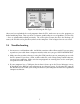
Figure 2.4: Selecting the EL6 Type After you have uploaded the wash programs from the EL6, make sure to save the program set before modifying them. That way there is a known good backup in case of problems. Use the File — Save as command described previously. The easiest place to store the file is the Desktop. Of course, the EL6 file can be placed anywhere on the computer – Don’t forget where it was saved! 2.4 Troubleshooting 1. You must use a null modem cable.
Chapter 3 EL6 Win 2 Introduction Figure 3.1 on page 9 shows a typical screen view. The EL6 window area is divided into the following panels: • The section at the top left displays the list of programs and their associated cycles.
Figure 3.
• File — Save =⇒ Save current window content into a file using the current file name • File — Save as =⇒ Save current window content into a file allowing to set the name • File — Print =⇒ Print the current window content • File — Open language =⇒ Open a language file • File — Import .
Figure 3.2: EL6 New Formula Dialog Box Always select the middle button, EL6 Inverter for B&C Technologies machines. Once the file is imported, it can be modified and handled normally. When saved, the file will be saved in the new .L62 format. Figure 3.3: Import .EL6 Format Dialog File — Print When this command is executed, the following window shown in figure 3.4 on page 12 opens. It is used to select which portions of the file content are to be printed.
Figure 3.4: Print Dialog Figure 3.
File — Open language file The Language File allows some customization of the EL6 Win 2 interface. The English.lng language file (the standard language file) has been modified to show the function of each relay. For example, all B&C Washer-Extractors use Relay 13 as the balance signal relay. When looking at an extract cycle, Relay 13 is identified as the balance relay. If programing the EL6 via the built in keypad, Relay 13 is simply called Relay 13.
Chapter 4 The Cycles Window Remember that Programs are made up of Cycles, and Cycles are made up of Steps. The Steps are where water valves are turned on, chemical assignments are made, etc. In order for the washer to do anything, cycles must be programmed. Typically, most cycles are created as a wash bath - i.e.
Figure 4.
4.1.2 Compound Rinses Rinses and other cycles may be combined into a larger single cycle containing many steps. Rinse 10, 11, 12, and 13 as shown in the stock programs are examples of this idea. Refer to figure 4.2 on page 17 for details. By combining several rinses into one cycle, it is possible to do more baths under the 15 cycles per program limitation.
Figure 4.
Program 1 now contains only 7 cycles, leaving room for plenty of customization in the wash process. A Note about modifying Bath cycles: Modifying a cycle changes that cycle in whatever program that cycle is used. For example, if Wash 11 is used in Program 1 and Program 2, changes to Wash 11 would affect both Program 1 and Program 2. Use this feature to advantage! Much time can be saved through similarities in wash programs. 4.1.
the imbalance occurred. The EL6 will retry 3 times before terminating the program. This cycle should not be added to any program. 4.2.2 Spin 9 - Drain with no spin Typically, a drain will follow a bath in a standard wash formula (no surprise!). The easiest way to achieve this is by using the already programmed Spin 9. Adding drain steps in each bath would waste many steps over simply using the Spin 9 routine (only 2 steps).
and can be pasted as a new cycle. To paste the cycle, select the cycle group header in which the cycle is to be pasted. For example, if the cycle will be a Wash cycle, click on and select the Wash header, located above all the other wash cycles. See figure 4.3 on page 20. Notice that the header, Wash, is highlighted. Now right click on Wash and click Paste Cycle in the sub-menu. The pasted cycle will appear as the next available cycle number at the bottom of the list of Wash cycles. Figure 4.
4.7 Working with Steps The steps are the building blocks used to create a wash cycle. Each cycle can contain up to 100 steps but remember that there are only 400 total steps allowed in total. The cycles window is shown in figure 4.1 on page 15. Everything that happens during the wash cycle is controlled discreetly by a step – one function at a time is performed (Fill ⇒ Chemical Dose ⇒ Top off ⇒ Agitate).
Each step is split into 5 segments: 1. Outputs 2. Special Functions 3. End of Step 4. Others 5. Motor 4.7.1 Outputs The outputs are fairly self explanatory. When a particular output is turned on, that function is activated. Each relay output can be turned off or on by double clicking in the cell, or by pressing the spacebar when the cell is highlighted. 4.7.2 Special Functions Heating, Fill to temperature, and Cooldown are controlled by this section. Double clicking a function enables that function.
Figure 4.
Table 4.
4.8 Inserting a New Step A new step is created by selecting an existing step, then right clicking the step. When the submenu appears, click Insert step or press the Insert key on the laptop keyboard. Refer to figure 4.5 on page 25. A new blank step is now inserted. Notice that all existing steps shift one column to the right and that the new step has replaced the previously highlighted step (Step 2 was highlighted, and now the new step is Step 2 and the previous Step 2 is now Step 3). Figure 4.
or another cycle in the program group. Right click, and select Paste step from the sub-menu. Just as with the Insert Step function, all existing steps shift one column to the right and that the pasted step has replaced the previously highlighted step. 4.11 Enabling/Disabling Cells In order to change the function of a step type, the existing end step function must be disabled before the new condition can be enabled. The EL6 allows only one end step condition per step.
4.12.2 Fill to Temperature The Fill to Temperature function is used to fill the machine to a temperature between the incoming cold and hot water supply lines. Enabling the Fill to Temperature function will display the submenu shown in figure 4.7 on page 27. Enter the water level (in cm of water), desired temperature (in degrees Celsius), and the allowed time. The EL6 will modulate the cold water and hot water valves to maintain the programmed temperature to the given level in the alloted time. Figure 4.
4.13 Creating a Heat Cycle Any cycle can be converted to a heating cycle by inserting a step after the fill, and setting the end step condition to a temperature (See Step 2 in figure 4.9 on page 29). Step 1 - Fill to a water level with hot water. Heat is on, and will engage when a minimum water level is met. Watchdog timer of 5:00 allows time to fill before an alarm is generated. Step 1 ends when the water level is reached. Step 2 - Heat output is on.
Figure 4.
Chapter 5 Motor Modes Motor Modes are used to set the agitation profile for each step. There are 5 stock motor modes used: • Mode 1 – Standard wash agitation: 16 seconds forward, 4 seconds pause, 16 seconds reverse • Mode 2 – Gentle wash agitation: 4 seconds forward, 16 seconds pause, 4 seconds reverse • Mode 3 – Soak agitation: 5 seconds forward, 115 seconds pause, 5 seconds reverse • Mode 14 – Reverse only: Used in the rebalancing function after an unbalance condition.
Chapter 6 Creating/Modifying/Deleting Programs 6.1 Creating a New Program Once a library of cycles is in place, a new wash program may be created. To create a new wash program, click on any existing program, then right click that program and select Insert program from the sub-menu. Alternatively, press the insert key on the laptop keyboard. A new blank program is created at the end of the existing program list. The new program will be numbered with the next available unused number.
Figure 6.1: Creating a New Wash Program 6.2 Modifying a Program As mentioned in the previous section, wash cycles may be added to existing programs through dragging and dropping. To remove a cycle from a program, click on the cycle to be removed so that it is selected. Right click the cycle, then click Delete program or cycle, or press the Delete key on the laptop keyboard. Make sure the desired cycle is selected before deletion – there is no undo! 6.
Chapter 7 Information Window The information window is located at the bottom right of the EL6 Win 2 window. During file save or file open operations, the EL6 Win 2 software error checks the file. During this procedure, the information window will change and give details about the progress of this error check.
• Sending data • Receiving data – Warning message Includes: • Reminder to put the EL6 in communication mode - function 144 – Error message which stops an action in progress.
Chapter 8 Maintenance Functions The maintenance functions are located in the maintenance area, located directly below the program window on the lower left of the EL6 Win 2 window. Refer to 8.1 on page 35 for details. If the items in the maintenance area are hidden, hover the mouse on the bar just over the red ”‘squiggly”’ line in the lower left of the window. The mouse cursor will change, and the bar can be dragged up, revealing the maintenance area. Figure 8.
• Number of outputs Displays the EL6 configuration. Should ALWAYS say 24. Anything else and your programs WILL BE CORRUPTED. Recovery is possible, but embarrassing for the poor soul that makes this error. Read only. • Total Programs The total number of programs this EL6 control has executed, not including partial programs. Take care when transferring programs to a machine in use. If the stock programs are transferred to the machine, this counter will be overwritten.
• Max Spin RPM Sets the scaling so that the control can properly control the inverter drive. Adjustment of this parameter will very likely cause the machine to never extract. Other speeds will be off, but the dead giveaway is no extract. Do not adjust. • Max Spin water level Should never need adjustment. Setting this lower than 10cm can cause the machine not to spin. Setting it to 0cm will just about guarantee that the machine won’t spin.
Notes
Notes
More information is available on our website: www.bandctech.