Washer-Extractor EL-6 Computer Programming and Operating Instructions PROGRAM N? INS 1 TEMP TEMP PROBE FAULT BALANCE RETRY POWER FAILURE DEC 2 LEVEL INC 3 TIME 4 5 6 ADVAN 7 8 9 ENTER DEL RESET PAUSE 0 PN 230-004 B&C Technologies Panama City, FL (850) 249-2222 (850) 249-2226 FAX www.bandctech.com Revision 2.
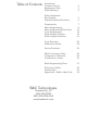
Table of Contents Introduction Customer Service Replacement Parts Quick Reference 3 3 4 Safety Information Key Symbols Important Safety Information 5 6 Programming Motor Programming Motor Programming Flow Chart Cycle Programming Wash Program Creation Wash Program Flowchart 7 8 10 14 19 21 Cycle Execution Malfunction Alarms 22 24 Service Functions 25 Metric Conversion Chart Centigrade to Fahrenheit Centimeters to Inches 29 29 30 Blank Programming Chart 31 Water Level Guide Speed Guide Appendix
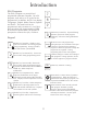
Introduction EL6 Computer 7 The EL-6 Computer is a powerful and programable solid state controller. Up to 30 programs, each with up to 15 cycles can be programmed. In addition, the EL-6 can display 5 languages - English, Italian, German, Spanish and French. The water level can be programmed, and is accurate to 1 cm (0.4 in). Spin speeds are fully programmable in RPM. In the event of power failure, the operator is prompted to continue the cycle, or abort it.
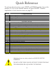
Quick Reference To perform these functions, press START and RESET together, then at the prompt (n?), key in the desired number, the press ENTER. Detailed explanation of each function starts on page 25.
Key Symbols Anyone operation or servicing this machine must follow the safety rules in this manual. Particular attention must be paid to the DANGER, WARNING, and CAUTION blocks which appear throughout the manual The lightening flash and arrowhead within the triangle is a warning sign alerting you of the presence of dangerous voltage. The exclamation point within the triangle is a warning sign alerting you of important instructions concerning the machine and possible dangerous conditions.
Important Safety Information SAFETY CHECK LIST Before machine is placed in operation, the door safety interlock must be checked for proper operation as follows: Before Initial start up of a B&C washer – extractor perform the following safety check: A. When the washer is energized electrically and in operation, the loading door must be locked in the closed position. Verify this by attempting to open the loading door when the machine is operating.
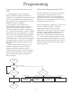
Programming Programming the EL-6 takes place on three levels: A Note about Programming the EL-6: The EL-6 comes from the factory with several stock programs already entered. See the separate document, EL-6 Stock Program List for details. It is by far easier to modify these existing cycles and programs than to start from nothing and create your own. 1. Programming motors (Function 45) Allows 15 different agitation profiles to be created.
Programming Motor Programming To access the motor programming mode, press START and RESET together. The display shows: Pressing ENTER will store the motor timing routine and the display will change to request a new access code: n? n? Enter 45 at this prompt, followed by the ENTER key. For two seconds, the display will show: Enter 45 at the prompt to program additional motor timing sequences as required. Pressing RESET instead of ENTER will exit programming.
Programming Motor Programming continued The minimum pause time that can be programmed between forward and backwards is 2 seconds. The maximum time is 239 seconds. Notes on Motor Programming There are a number of different modes available for motor programming: 1. Forwards - Pause - Backwards Cylinder speed is programmed during cycle programming. In this mode, each step can be programmed with different values if desired. T. FORWARD = XXs T. PAUSE = XXs B&C Stock Motor Assignments T.
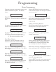
Programming Motor Programming Flow Chart POWER PROGRAM # START + RESET RESET n? 45 ENTER *EDIT MOTORS* MOTOR N NO EXIST? YES T. FORWARD = S EXISTING! # OF SEC ENTER ENTER T. PAUSE = S T. FORWARD = S0 # OF SEC ENTER INC DEC T. PAUSE = XXs T. BACKWARDS = S # OF SEC ENTER DEC INC T.
Cycle Programming Sequence To turn on a function, press Enter, to turn off a function press Reset. Press Enter to edit a numerical value (RPM, Time, etc.). Note: Setting a function to zero DOES NOT disable that function. Cool Down More information on page 15 Min. Level ENTER INC INC 3 Bal. Load 3 More information on page 16 Level INC INC 3 Temp. INC Yes to turn on the cold water valve. No means the valve is off. WDT Yes to turn on the hot water valve. No means the valve is off.
Cycle Programming Sequence To turn on a function, press Enter, to turn off a function press Reset. Press Enter to edit a numerical value (RPM, Time, etc.). Note: Setting a function to zero DOES NOT disable that function. Hard Water Yes to turn on chemical signal 5, and flush cup 5 in the supply dispenser, if equipped. No means the supply is off. INC 3 Relay 16 Not Used INC 3 Relay 11 Yes turns on Auxiliary Fill. No means the valve is off.
Cycle Programming Sequence To turn on a function, press Enter, to turn off a function press Reset. Press Enter to edit a numerical value (RPM, Time, etc.). Note: Setting a function to zero DOES NOT disable that function. Relay 20 Yes to open Auxiliary Drain, if equipped. No means drain is closed. Example Cycle Construction: Step 1 (Fill Step) Turn on hot, cold or both. Turn on Motor, and enter RPM.
Programming Cycle Programming New Cycle Creation Cycle libraries can be created for later use in the Wash programming step. When the machine is stopped, press the START and RESET buttons together. The display is: If the cycle you chose does not exist, you will be taken directly into the programming mode. For two seconds, the display will show: START STEP 1 n? The display then changes to: Using the keypad, type 12 and press ENTER.
Programming Cycle Programming continued To activate the Drain and end Step 1, press ENTER. Pressing INC or DEC will scroll through the other functions to end the step. The step can end with a Water Level, a Water Temperature, or an elapsed Time. Select one of the functions by pressing ENTER changes the display and prompts you to enter a value for the particular function. Example The display now shows: STORE? Pressing STOP will cancel the programming and abort any parameters you have entered.
Programming Cycle Programming continued Load Balancing / Temperature Controlled Fill Motor For the motor function, after pressing ENTER, you are asked to enter a motor function (programmed earlier, see pages 8-10). When you have confirmed the selection with ENTER, the display shows: The Load Balancing option is essentially a temperature controlled, or modulated, fill. Cold and Hot water are added to the machine while the temperature and level are monitored.
Programming Cycle Programming continued You may now proceed to program the new step using the techniques described earlier. After confirming storage of the new steps, press STOP. N Remove one or more of the steps from the existing ones. Proceed by pressing ADVAN as describe above in (3).
Programming Example Cycle The figure at the right shows a typical fill bath.
Programming Wash Program Creation When the machine is stopped, press the START and RESET buttons together. The display is: C2>? At this prompt, press ENTER. The choice of cycle will be displayed as previously. Programs can be compiled with up to 15 cycles chosen from those in available in the cycles library (see the EL6 Stock Programs Listing). The same cycle can be used repeatedly in a wash program. After you are through programming, and have confirmed the last cycle, press STOP to terminate programming.
Programming Wash Program Creation continued STOP key when the display changes to: Note: The factory programs and cycles can be altered at will. There is no way to restore the factory programming without manually inputting them, or via download with the EL6 Win 2 programming software, available on the technical service page of our website. STORE? Confirm by pressing the ENTER key. The cycle in question will be deleted, and the cycles following will be decremented by one.
Programming Wash Program Creation continued PROGRAM N. START + RESET n? CODE 27 EDIT PROG. No. NUMBER EDIT PROG. No. 1 ENTER NO EXIST? YES NOT FOUND! EXISTING! 2 SECONDS STOP C1>? C1>PREWASH=2 ENTER C1>PREWASH=? C1>WASH=? C1>SPIN=? C1>RINSE=? C1>UNROLL=? DEC INC STOP DEC C1>WASH=1 DEC INC STOP INC C1>RINSE=4 DEC INC ENTER C1>PREWASH=n NUMBER INC C1>PREWASH=n.
Execution Wash Program Execution After power is applied to the machine, and the internal diagnostics are complete, the machine is ready for a program to be chosen. The display will show: will change, for 3 seconds, show the required step temperature for advance. Pressing INC or DEC allows modification of the value for the step. Pressing LEVEL allows you to see the current water level. Pressing the TIME key shows the watch dog timer (WDT) value for the current step. PROGRAM N.
Execution Wash Program Execution Partial Program Water Level Refresh A program can be partially run. After selecting the program you wish to execute, the display will show: While a program is running, if the water level drops to a level which is 3cm below the target level, cold water will automatically be added to replenish the level. PRWH 1 EXECUT.? Unbalance Instead of pressing ENTER to execute the program, press the ADVAN key. The cycles within the program will be displayed incrementally.
Execution Wash Program Execution Malfunction Alarms > Faulty drain valve > Problem with water level tube Pressing START will continue the program, while RESET will cancel the program. During Drain > Drain valve blocked > Drain hose blocked > Faulty Drain Valve Press RESET to end the program. The state of the water temperature and water levels are constantly monitored to prevent functioning problems with these devices.
Service Functions Access Functions All machine functions are accessed by pressing START and RESET simultaneously. At the changed prompt, key the required function, then press ENTER. Maintenance Request After 450 wash programs have completed, the machine will call for maintenance: MAINTENANCE 12 Cycle (segment) Programming 27 Wash Programming 45 Motor rotation programming (agitation profiles). 144 Enables the EL6 communication mode so that programs can be downloaded and uploaded to the control.
Service Functions Access Functions continued Minimum Level for Heat Function 213 This function sets the minimum allowable water level for heat to activate. Upon entering the function, the value will be displayed. To modify, press ENTER. Type the new value, and press ENTER again to confirm. Maximum Spin Speed Function 201 This function allows you to display or modify the maximum spin speed. Upon entering the function, the display will show the current value. To exit without changing, press RESET.
Service Functions Access Functions continued Maintenance Required Function 218 This function sets the number of washes before the maintenance alarm is activated. The default value is 450. This means that after 450 wash programs have been completed, the maintenance alarm will be displayed. To change the value, use the INC or DEC keys. The value changes by 10 each time a key is pressed. You may hold down the key to change the number quickly. Once the desired value is reached, press the ENTER key to confirm.
Service Functions Access Functions continued Function 223 continued 5. ENTER The display now shows “COPY FROM CARD?” 6. Press ENTER The display now shows “COPY FROM CARD” followed by “COPY OK.” Disabling the Advance Key Function 225 This function disables the ADVAN key. This function toggles between enabled (YES) and disabled (NO). Default value is enabled (YES). Maximum Level in Spin Function 230 This function sets the maximum water level during execution of a spin.
Metric Conversions Fahrenheit to Centigrade F 86 87.8 89.6 91.4 93.2 95 96.8 98.6 100.4 102.2 104 105.8 107.6 109.4 111.2 113 114.8 116.6 118.4 120.2 122 123.8 125.6 127.4 C 30 31 32 33 34 35 36 37 38 39 40 41 42 43 44 45 46 47 48 49 50 51 52 53 F 129.2 131 132.8 134.6 136.4 138.2 140 141.8 143.6 145.4 147.2 149 150.8 152.6 154.4 156.2 158 159.8 161.6 163.4 165.2 167 168.8 170.6 29 C 54 55 56 57 58 59 60 61 62 63 64 65 66 67 68 69 70 71 72 73 74 75 76 77 F 172.4 174.2 176 177.8 179.6 181.4 183.
Metric Conversions Centimeters to Inches cm in cm in cm in cm in cm in 1 0.39 21 8.27 41 16.14 61 24.02 81 31.89 2 0.79 22 8.66 42 16.54 62 24.41 82 32.28 3 1.18 23 9.06 43 16.93 63 24.8 83 32.68 4 1.57 24 9.45 44 17.32 64 25.2 84 33.07 5 1.97 25 9.84 45 17.72 65 25.59 85 33.46 6 2.36 26 10.24 46 18.11 66 25.98 86 33.86 7 2.76 27 10.63 47 18.5 67 26.38 87 34.25 8 3.15 28 11.02 48 18.9 68 26.77 88 34.65 9 3.54 29 11.
Blank Programming Chart Prewash: Wash: Funct ion Cooling Load Balanced Drain Cold Water Hot Water Heating Detergent 1 Detergent 2 Detergent 3 Detergent 4 Hard Water Relay 16 Relay 11 Relay 12 Relay 13 Motor Speed RPM Relay 17 Relay 18 Relay 19 Relay 20 Relay 21 Relay 22 Relay 23 Relay 24 End Step Level cm Temp C WDT m:s Time m:s 1 2 Cooling Level min cm= Level max cm= Temperature C= WDT m:s : Notes: 3 4 Rinse: 5 6 7 8 Spin: Unroll: S t ep 9 10 11 12 13 14 15 16 17 18 19 20 21 22 Temperature
Water Level Guide Machine HE-30/35 HE-40/45 HE-60/65 HE-80/85 SP-40/45 SP-60/65 SP-100/110 SP-130/135 SP-155/165 SP-185/195 SB-60 SB-80 SB-155 SB-225 SB-300 SB-480 SI-110 SI-135 SI-200 SI-275 SI-300 SA-475 HP-60/65 HP/HI-85 HP/HI-125 8 cm 6 cm 5 cm 8 cm 16 cm 18 cm 20 cm 24 cm 24 cm 28 cm 18 cm 19 cm 24 cm 28 cm 30 cm 34 cm 24 cm 26 cm 28 cm 30 cm 30 cm 34 cm 18 cm 24 cm 26 cm Low 3.0 in 3.4 gal 2.5 in 3.4 gal 2.0 in 3.3 gal 3.0 in 5.4 gal 6.4 in 6.4 gal 7.0 in 9.1 gal 7.9 in 14.5 gal 9.5 in 25.4 gal 9.
RPM-G Force Guide EL6 PROGRAM SPEEDS IN RPM FROM G-FORCE POINTS Machine SP-40/45 SP-60/65 SP-100/110 SI-110 SI-135 SI-200 SI-275 SI-300 SI-450 HP-60/65 HI/HP-85 HI/HP-125 0.4 G 32.4 30.1 27.6 27.6 25.6 24.7 23.3 23.3 21.0 30.1 28.0 26.0 0.8 G 45.9 42.6 39.0 39.0 36.2 35.0 32.9 32.9 29.6 42.6 39.6 36.8 1.0 G 51.3 47.6 43.6 43.6 40.5 39.1 36.8 36.8 33.1 47.6 44.3 41.1 1.5 G 62.8 58.3 53.4 53.4 49.6 47.9 45.1 45.1 40.6 58.3 54.2 50.3 3.0 G 88.9 82.4 75.6 75.6 70.1 67.8 63.8 63.8 57.4 82.4 76.7 71.
Appendix A Creating a Heat Cycle Any cycle can be converted to a heating cycle by inserting a step after the fill, and setting the end step condition to a temperature (See Step 2 in the illustration to the right).