
Data Sheet
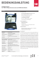
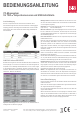
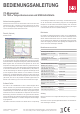
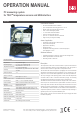
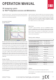
Table Of Contents

OPERATION MANUAL
Technical changes reserved
0141 0316-31 18.10.2021
PC measuring system
for TSIC
TM
temperature sensors and USB-interface
Connection assignment
The TSic™ temperature sensors are connected via the included TSic™ con-
nection cable. On the module side, the connection cable is protected against
polarity reversal, on the sensor side, the contact socket is marked with a
white dot. This point marks the white wire (GND/PIN3) of the connection
cable.
WINDOWS-Software RECORDER
With the help of this program, the measured values can be received through
the USB-interface and displayed on the PC. The displayed le is compatible
with any desired spreadsheet program, with which it is possible to further pro-
cess, statistically evaluate or visualise the measurement data.
In addition, the PC-Software also determines the minimum, maximum and
average value from the measured values.
System requirements: Windows 98, 2000 or XP, RS232 or USB-interface.
Generally, older PCs are also suitable.
Important hint: First connect the USB-Version to the PC after installing the
software. This simplies driver installation and enables „Plug&Play“ feature.
Installation: Download: https://download.bb-sensors.com/index.php/login
Login: bb-shop Password: BBshop#2017
Manual Installation: Insert the enclosed CD into your drive and select „Run“
in the start-menu and then browse to select the le ‚setup.exe‘ under the path
LW:\software\RECORDER\TEMPLOG\disk1. Then follow the instructions of
the installation program.
First time operation: Connect the temperature measuring system to the
USB-interface of a PC. After rst time run of the software, go to menu option
„settings“ and select device type as „TSIC-LABKIT“ and also select the type of
interface to be used under „connections“ (Note: For USB-version, mention the
virtual COM-port specied during driver installation). The remaining settings
(Data rate, Parity, Start and Stop bit) are automatically selected and need
not be changed. If the connection is established, the data communication ap-
pears on the terminal window. Then select „Close“. The current settings will
be stored.
If you are not able to establish data link between PC and the measuring probe,
then rst please check the USB cable connection to the PC. Further informati-
on on debugging is available under FAQs on the CD.
Data recording: First activate all the hooked up measurement channels that
are to be recorded. In ‚Text 1‘ and ‚Text 2‘, you can enter a description, which
has to appear as heading on the top of data le. The data is recorded in a le,
which is declared as path in the ‚Start‘ button. The recording begins with the
‚Start‘ button.
EXCEL™: The created le is compatible with CSV-format. In order to display
the measured data, you can use graphic tools, for example, the diagram-as-
sistant. However, other programs can also be used to graphically represent or
evaluate the measured data.
Internal data transfer
The communication between PC and measuring probe takes place serially
by means of a COM port emulation. Therefore, it is very simple to link the
measurements to our own software, programming knowledge presupposed.
For the used USB UART FTDI 232, drivers are available for Linux, MAC or
even PDAs. Further information is available on website of the manufacturer
www.ftdichip.com
The interface works on a data rate of 4800 Baud, 8 Data bits, No parity and
one Stopbit. Further information on data protocol can be downloaded from our
homepage.
Further application areas
Although the product is primarily intended as a Evaluation Kit for the innovative
Pin No. Name Description Wire
1 V+ Operating voltage (3...5,5 V) Yellow
2 Signal Temperature ZACwire Green
3 Gnd Ground White
B+B Thermo-Technik GmbH | Heinrich-Hertz-Straße 4 | D-78166 Donaueschingen
Fon +49 771 83160 | Fax +49 771 831650 | info@bb-sensors.com | bb-sensors.com
2 / 3