
Datasheet
DATA SHEET
Technical changes reserved
0141 0316-24 06/2014
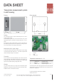
Temperature measurement system
in wall housing
For further information, please visit our website:
www.bb-sensors.com
Boring template
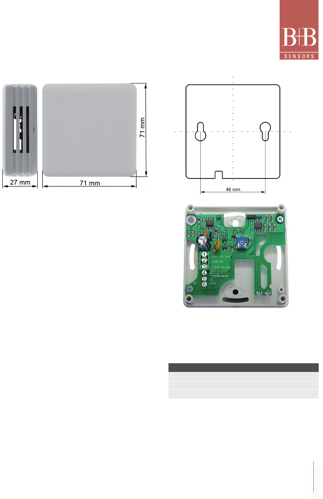
1 +DC 24 V
2 GND
3 TEMP 0-10 V
Temperature measurement 0…10 V
The measurement of the output signal should be done with separate
signal ground in order to avoid measurement errors of the ground con-
nection due to voltage drop.
Drawing
Feeding
The measurement probe can be fed alternatively with AC or DC or
unsifted, rectied voltage.
At AC-feeding the ground mark of the transformator has to lay on the
signal ground and the connectiion of further probes has to occur in-
phase.
At feeding with unsifted, rectied voltage you have to switch Minus on
the refreence ground and Plus on the +DC/AC 24 V. A wrong connec-
tion can lead to failure or to damage of the electroics.
Measurement of the signal voltage
To avoid measurement failures by the cable resistance and the supply
current through the earth cable in the 0…10 V model a separate earth
cable for the signal voltage is to be planned.
Connection
For the connection should be preferentially used screened connection
cables. Especially in EMI disturbed environment. The shielding is to
be grounded. Please check before connecting that the supply voltage
agrees to the specied operating voltage (data sheet).
Warranty
You get 24 month warranty on our high class measurement probes.
Modications to the elctronics will result in loss of the warranty claims..
Calibration service is excluded from warranty.
Pin Function Description
1 +DC/AC 24 V Operating voltage
2 GND 0 V Reference potential
3 TEMP 0...10 V Temperature signal 0…10 V
B+B Thermo-Technik GmbH | Heinrich-Hertz-Straße 4 | D-78166 Donaueschingen
Fon +49 771 83160 | Fax +49 771 831650 | info@bb-sensors.com | bb-sensors.com
2 / 2