
User manual

OPERATION MANUAL
Technical changes reserved
0141 0316-41 21.08.2015
Evaluation electronics for
ceramic pressure sensors - DS-MOD-
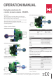
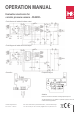
Connection
The pressure sensor is connected to the four pin socket strip as
shown in the illustration. The connection cable can be directly inser-
ted into the spring contacts of the socket strip.
The connection of a Pt1000 is optional and only required, if the digital
setting with temperature compensation is being used.
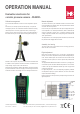
The connection of operating voltage and instrument is done as shown
in the following diagrams:
Voltage connection diagram
with absolute pressure sensor
with relative pressure sensor
Current connection diagram
with absolute pressure sensor
with relative pressure sensor
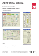
Connection terminals
Pin Voltage output Current output
1 +DC 12 … 24 V +DC 12 … 24 V
2 GND OUT 4 … 20 mA
3 OUT 0 … 10V ---
Bridge input
Signal Function
SUP+ Supply to measuring bridge +
OUT- Output of measuring bridge -
SUP- Supply to measuring bridge -
OUT+ Output of measuring bridge +
Pt1000
Signal Function
Pt1000 Pt1000 ASIC input
GND Ground
The Pt1000 is only to be tted, if the electronics is be digitally calibra-
ted with temperature compensation.
Calibration plug connector
Signal Function
+5V ASIC Operating voltage
OWI One Wire Interface and analog
output
IO2 Digital switch output or PWM-
Signal
SCL I2C Clock
SDA I2C Data
GND Ground
Caution! The ASIC can be damaged by wrong connection at the
calibration plug connector. Please only use our “ZMD Labkit“ on the
module for calibration!
B+B Thermo-Technik GmbH | Heinrich-Hertz-Straße 4 | D-78166 Donaueschingen
Fon +49 771 83160 | Fax +49 771 8316-50 | info@bb-sensors.com | bb-sensors.com
2 / 5