
User manual

OPERATION MANUAL
Technical changes reserved
0141 0316-120 20.04.2016
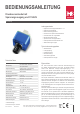
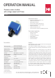
Pressure sensor module
with voltage output and I²C-bus
Standard model
The module is congured as follows:
• Operating voltage range 6 to 15 V / 3 mA
• Calibrated at 8.0 V
• I²C Interface for pressure
• Voltage output 0...5 V
• Temperature measurement with Pt1000
Application notes
Supply with 5 V is possible, if analogue output is not used. The calib-
ration at factory is done at 8 V. The specied technical data is valid at
this operating voltage. Other congurations and special calibration as
per customer requirements are possible. While connecting the measu-
ring probes over longer routes, the used I²C-Bus external to the device
should not be used internally, in order to avoid coupling of interferen-
ces to the device internal communication. The EMV-guidelines are to
be followed and shielded lines are recommended.
A RESET of the pressure sensor can be initiated by a short time inter-
ruption of the operating voltage. If the operating voltage can be swit-
ched off, then the pullup resistance of the I²C bus must be connected
to the switched voltage. To simplify your product development, a com-
munication board and an USB-I²C-adapter is available. Please send
us your enquiry!
Operating voltage
Standard supply is 6 to 12 V operating voltages which are stabilised
in the module to 5 V. The 5 V operating voltage also serves as the
reference level for the digital I²C communication.
Voltage output
On PIN1, the measured pressure is given out as analoge voltage sig-
nal. The voltage range of 0...5 V represents the measuring range: 0 V
corresponds to the smallest measured value or lower limit, 5 V repre-
sents the measured range limit or upper limit.
The connection impedance should not be less than the minimum value
of 10 kΩ. The output impedance is around 50 Ω. The output is protec-
ted against short circuit transients. External voltage at the output can
lead to a damage of the ASIC and should be certainly avoided.
I²C-Interface
The communication corresponds to the standard I²C protocol. All
technical specication of the protocol can be obtained from the docu-
mentation “Serial Interface of B+B ASIC“. The documentation is availa-
ble on request or can be downloaded from www.bb-sensors.com.
The standard address of the component is 0x78, the component can
always be communicated with this address. The address is to be un-
derstood as a 7 bit address, left justied and with masked R/WBit is the
Read-address 0xF1.
Additionally, a second address can also be programmed during
conguration ex factory, through which the pressure sensor can be
addressed.
From this address 0x78 (7 bit address), 2 Bytes can be read. The fol-
lowing assignment is applicable:
Scaling of measured value
Byte 0 and 1 represent the pressure value and is transmitted as a 15
bit value (bit 0 - 14).
The most signicant bit (bit 15) is always 0 during normal operation and
in case of error, bit 15 is set to 1.
Following scaling is applicable for the measured values:
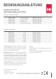
Pin strip connection layout
Data
0x78 Byte_0 MSB pressure
Byte_1
LSB pressure
Pressure
Numeric value over
I²C Interface
0x 0000...7FFF
dec. 0...32767
Physical value
as per model
Scaling P =V / 32768 * measuring range
Pin Title Function
1 OUT Voltage output
2 SDA
Serial data I²C
3 SCL Serial pulse I²C
4 GND Ground
5 VDD Operating voltage 6...12 V
B+B Thermo-Technik GmbH | Heinrich-Hertz-Straße 4 | D-78166 Donaueschingen
Fon +49 771 83160 | Fax +49 771 8316-50 | info@bb-sensors.com | bb-sensors.com
2 / 3