
User manual


Released 03/2008 Rights reserv ed f or change in technical data! HYGROSENS INSTRUMENTS GmbH Postf ach 1054 D-79839 Löf f ingen Tel: +49 7654 808969-0 Fax: +49 7654 808969-9
page 8
LEVEL CONTROLLER FOR
CONDUCTING LIQUIDS
5 Assembly, adjustment and configuration
5.1 Electrical connection
5.1.1 Safety instructions
Caution ! Touching the high voltage parts may lead to fatal dangers. The mounting
and maintenance operations should be carried out by only trained personnel, who are
authorised on the basis of technical training in this field. The applicable safety
regulations are to be duly followed! The switching device must be assembled in a
switching cabinet or in a fully closed plastic housing. Mounting and servicing
operations should be carried out only after switching off the voltage. The device
should be mounted only at dry locations!
Due to wrong tightening of screws of the connection terminals or by use of
inappropriate tool, the terminals can get damaged because of which the insulation or
the contact can get disturbed. Badly connected leads can come out during operation
and cause a serious risk to safety. Due to contact resistance at terminal connections,
there can be increased heat generation which can cause fire. Wrongly wired
connections can destroy electric components and cause other damages.
5.1.2 Lines to the sensor set-up
The RJ12-plug connector has been provided for direct connection of sensor lines to
the unit. The connector is led through a cable gland provided in the housing and
properly mounted through M16 threads. The connection of the ready sensor is to be
done as per enclosed data sheet.
The connection length of self made sensing set-up should not exceed 5 m. For short
connection lengths up to approx. 3 m, a simple unshielded cable (5-core) is quite
suitable. For larger lengths or in EMV-critical environment, shielded cables should be
used. The shielding should be connected to COM (reference electrode).
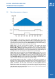
In long connection lines, the electrode input may change due to line capacitance. This
can be adjusted through potentiometers. If necessary, the adjustment should be
checked again after any modification in line length.
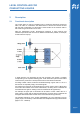
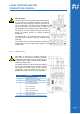
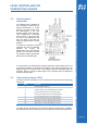
5.1.3 Operating voltage
12V/24V-AC/DC model: The operating voltage is connected
at the terminals “SUPPLY VOLTAGE“. The rating of nominal
voltage is mentioned on the PCB and also on the relay and
must be maintained as per specifications on the data sheet
in order to ensure an error free functioning. A too high
operating voltage can lead to damage of the device.
Extremely low or unstable operating voltage leads to
malfunctioning.
The device has a rectifier bridge after the input supply
connection. Hence polarity of input voltage is arbitrary.
However, if several devices are connected to the same
voltage supply, the connections should be done with same
polarity to avoid any potential difference in the medium.