
User manual


Released 03/2008 Rights reserv ed f or change in technical data! HYGROSENS INSTRUMENTS GmbH Postf ach 1054 D-79839 Löf f ingen Tel: +49 7654 808969-0 Fax: +49 7654 808969-9
page 5
LEVEL CONTROLLER FOR
CONDUCTING LIQUIDS
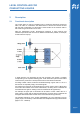
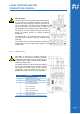
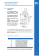
2.2 Operating sequence diagram
Initial condition : The reservoir is first empty. The electrode E1 is not in water
contact. Relay 1 is in closed position (because of this e.g. the inlet valve is open). The
water level rises in the reservoir. Water contact with the lower Electrode E1 (1) does
not change the relay status and only when Electrode E2 comes into water contact (2),
Relay 1 switches OFF (as an effect e.g. the inlet valve closes).
Upper level: If the level in the reservoir continues to rise further and reaches
Electrode E3, Relay 2 still remains in off state. After the water level reaches
Electrode E4 (4), Relay 2 is switched ON (and with that e.g. the outflow pump). When
the level falls and Electrode E4 is released free (5), the relay remains closed until
Electrode E3 is released free. (6). This means that between the upper switching ON
point E4 and the lower switching OFF point E3, there is a hysteresis gap.
Lower level: If the level continues to fall, the Electrode E2 becomes free (7). In the
reducing level direction, Relay 1 is kept in off state, till Electrode E1 is also out of
water contact (8). Only then Relay 1 closes. If again the water level is in rising
direction, Relay 1 remains closed even after water contact with Electrode E1 (9).
Only if Electrode E2 again comes under water contact, Relay 1 is switched OFF (10).
Hence, the lower level also has a provision of hysteresis margin.
The referred appliances “Inlet valve“ or “Pump“ are taken only as examples for
illustration of the working principle. What appliances are used finally depends on the
application. The switching behaviour of both the relays can be reversed through two
jumper connections. The two relay circuits work as level regulators and are
independent of each other. Hence, it is not necessary to use both the circuits, the
device is also suitable for controlling only one level. For this purpose, only two sensing
electrodes and a reference electrode are required. In such a case, the second channel
(relay and electrode inputs) is not used.