
User manual

Released 03/2008 Rights reserv ed f or change in technical data! HYGROSENS INSTRUMENTS GmbH Postf ach 1054 D-79839 Löf f ingen Tel: +49 7654 808969-0 Fax: +49 7654 808969-9
page 11
LEVEL CONTROLLER FOR
CONDUCTING LIQUIDS
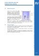
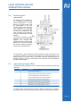
5.4 Configuration of operating mode
The switching polarity of the relay (Fill/empty) can be adjusted by two jumper plugs.
The jumper plug “MODE1“ is meant for Relay 1 (lower level) and jumper plug
“MODE2“ is for Relay 2 (upper level).
If connected in position 1-2, the relay switches ON with rising level and in position 2-3,
the relay switches ON with falling level.
5.5 Connection of user's own sensors
The following details are useful for persons with adequate knowledge of the
associated electronics. The applicable safety regulations shall be duly followed!
Connection and mounting operations shall be carried out only after switching off the
voltage supply.
The following instructions help in connection of your own sensors at the input socket
of electronics. However, this certainly needs necessary attention as operating voltage
is present at the socket also. Sometimes, wrong connection may lead to damage of
the components or result in failure of the module itself.
Touching the electronic components in switched off condition should also be avoided.
Electronic components can get damaged due to electrostatic discharge process. ESD
protection measures should be duly observed!
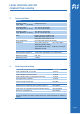
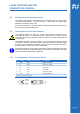
5.5.1 Pin configuration of input socket (RJ12)
Pin Function Colour (6 core cable ) Description
1 COM White Reference electrode
2 E 4 Brown Level 4 (E4), highest
3 E 3 Green Level 3 (E3)
4 E 2 Yellow Level 2 (E2)
5 E 1 Grey Level 1 (E1), lowest
6 COM Pink Reference electrode
Top view of contacts on the plug!