
User manual


Released 03/2008 Rights reserv ed f or change in technical data! HYGROSENS INSTRUMENTS GmbH Postf ach 1054 D-79839 Löf f ingen Tel: +49 7654 808969-0 Fax: +49 7654 808969-9
page 10
LEVEL CONTROLLER FOR
CONDUCTING LIQUIDS
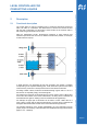
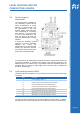
5.2 Switching point
adjustment
The switching point is adjusted as
per conductivity of water with the
preset potentiometers. In normal
practice, it is good enough to set
the potentiometer in the most
sensitive position (right side limit).
This corresponds to a switching
point of approx. 12 µS. This works
for most of the applications with
clean rain water or tap water. Ex
factory the potentiometer is central
adjusted.
If required, the sensitivity of each
electrode can also be separately
adjusted. By turning the
potentiometer in the anti-clockwise
direction, the electronics become
less sensitive and this gives better
results with contaminated water.
In normal practice, all potentiometers should be kept at the same position and only for
very diverse conditions of electrodes with respect to the reference electrode or for
different lengths of connection lines, it is practically required to separately adjust the
sensitivity. After any change in cable length of the connection lines, the adjustment
should be checked again.
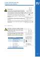
5.3 Light emitting diodes (LEDs)
The device status is indicated by a set of 8 LEDs which are placed at the lower edge
of the PCB:
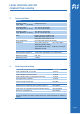
LED Function
P Power, Operating voltage 5 V
E Container empty, none of the electrodes are in contact
L1 Level 1 (first electrode from the container bottom)
L2 Level 2 (second electrode from the container bottom)
L3 Level 3 (third electrode from the container bottom)
L4 Level 4 (fourth electrode from the container bottom)
R2 Status Relay 2, for upper electrode pair E3 and E4
R1 Status Relay 1, for lower electrode pair E1 and E2
The LEDs are also provided on the front side for display of device status. In addition,
two pushbuttons are also provided by which the relays can be manually switched ON.