Ordering No.
HYGROSENS INSTRUMENTS GmbH Postf ach 1054 Rights reserv ed f or change in technical data! 1 General dangers and precautions ............................................................................................ 2 1.1 Instructions regarding documentation................................................................................. 2 1.2 Safety instructions.............................................................................................................. 2 2 Description...................
Instructions regarding documentation Please carefully read the following instructions before putting into operation! The symbols used in the operating manual are to make you careful, before hand, regarding safety considerations and dangers. But, in no way, these symbols can substitute the text of the associated safety instructions. Therefore, the instructions should also be always read in full detail! This symbol indicates likely danger for persons, material or environment.
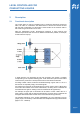
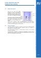
2 Description 2.1 Functional description The control device is used for regulating level of conducting liquids like supply line water, rain water or condensate. The measurement of level in the reservoir is done with the help of electrodes, for which either contact surface of the reservoir walls or self made rod type electrodes can be used. According to water contact, the fill level is indicated through 4 green LED´s L1 to L4. If the reservoir is completely empty, the red LED glows.
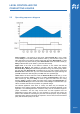
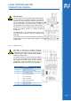
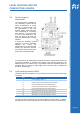
Upper level: If the level in the reservoir continues to rise further and reaches Electrode E3, Relay 2 still remains in off state. After the water level reaches Electrode E4 (4), Relay 2 is switched ON (and with that e.g. the outflow pump). When the level falls and Electrode E4 is released free (5), the relay remains closed until Electrode E3 is released free. (6). This means that between the upper switching ON point E4 and the lower switching OFF point E3, there is a hysteresis gap.
The model in housing is provided with a 230V AC power supply and a control unit with LEDs for level indication and also pushbuttons for manual switching of the relays. Typical areas of application: Water harvesting/monitoring in rain water cisterns, monitoring of condensate tubs and compressor pressure chamber, boiler, fountains and wells, cattle watering places, control of pumps. 2.
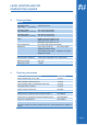
Operating voltage Type –230V (15 65 46) 230VAC/5 VA max. Operating voltage Type –MOD12V (15 65 19) 12V..15V DC 65 mA max. 11V..14V AC 80 mA max. Operating voltage Type –MOD24V (15 65 33) 22V..28V DC 45 mA max. 15V..25 V AC 60 mA max.
Electrical connection 5.1.1 Safety instructions Caution ! Touching the high voltage parts may lead to fatal dangers. The mounting and maintenance operations should be carried out by only trained personnel, who are authorised on the basis of technical training in this field. The applicable safety regulations are to be duly followed! The switching device must be assembled in a switching cabinet or in a fully closed plastic housing.
The terminal PE is not connected to the device and is only used to fix or clamp the PE wire. Its wiring is not necessary. The container with the medium should be grounded by suitable means to protect against high voltages in case of malfunction. 5.1.4 Load circuit The safety of load circuit, if required, should be taken care of through some external protection arrangement. (max. 5A NO contact, 2A NC contact). To switch higher currents, corresponding switching elements should be used.
If required, the sensitivity of each electrode can also be separately adjusted. By turning the potentiometer in the anti-clockwise direction, the electronics become less sensitive and this gives better results with contaminated water. In normal practice, all potentiometers should be kept at the same position and only for very diverse conditions of electrodes with respect to the reference electrode or for different lengths of connection lines, it is practically required to separately adjust the sensitivity.
If connected in position 1-2, the relay switches ON with rising level and in position 2-3, the relay switches ON with falling level. 5.5 Connection of user's own sensors The following details are useful for persons with adequate knowledge of the associated electronics. The applicable safety regulations shall be duly followed! Connection and mounting operations shall be carried out only after switching off the voltage supply.
Construction of sensor The sensor can be constructed in various ways: Electrodes of stainless steel rods, hanged from top into the medium, are ideally suited for this purpose. The reference electrode is in the middle of the 4 diagonally arranged sensing electrodes which are placed in a span of approx. 1-5 cm. The spacing should be wide enough so that no drop of liquid sticks back to the rods when the level falls down. These electrodes are practically maintenance free.
Prerequisite for the fulfilment of guarantee service is that the details of defect should be informed to us immediately and within the stipulated guarantee period. Of course, damages due to unintended use or non-compliance of operating instructions are excluded from this guarantee coverage. Moreover, defective sensors or sensing units and also calibration service are not covered in the guarantee. The serial number on the product should not be changed, damaged or removed.
79843 Löffingen, Germany The technical information in this document has been checked with adequate care at our end and is intended to inform about the product and its applications. The descriptions are not to be understood as assurance of the defined characteristics of the product and should be checked by the user for the intended application. Any possible industrial third party patent rights are to be considered. Issued March 2008 - This documentation supersedes all previous editions.