
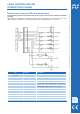
Circuit diagram

LEVEL CONTROLLER FOR
CONDUCTING LIQUIDS
Ausgabe 09/2006 Technische Änderungen vorbehalten! HYGROSENS INSTRUMENTS GmbH Postfach 1054 D-79839 Löffingen Tel: + 49 7654 808969-0 Fax: +49 7654 808969-9
Connection of external LEDs and pushbuttons
The connection of your own components shall be done at your own risk and is outside the guarantee
coverage!
External LEDs or pushbuttons for switching the relays can be connected on the terminal strip at the lower
edge of the PCB. A ready made control unit for 12/24V-model is available with us as accessories.
Pin Function Description
1, 2,5, 6,
7, 8, 17, 18
NC unused
3 5V Stabilised operating voltage 5V
4 15V Unstabilised operating voltage 15V
9 LED SW R2 LED and Relay 2 switch ,
switching against GND, red LED against +15V with R
v
4.7k
10 LED SW R1 LED and Relay 2 switch,
switching against GND, red LED to +15V with R
v
4.7k
11 LED 4 LED for level 4, LED green to +5V with R
v
1k
12 LED 3 LED for level 3, LED green to +5V with R
v
1k
13 LED 2 LED for level 2, LED green to +5V with R
v
1k
14 LED 1 LED for level 1, LED green to +5V with R
v
1k
15 LED EMPTY LED for level “Empty“, LED red to +5V with R
v
1k
16 GND Reference potential