
User manual


MANUALS
Technical changes reserved
0141 0316-112 05.2014
Level controller for conducting liquids
WLS-GEH230V
3.5 Connection of user‘s own sensors
!
The following details are useful for persons with adequate knowledge of the associated electronics. The applicable safety regulations
shall be duly followed! Connection and mounting operations shall be carried out only after switching off the voltage supply.
The following instructions help in connection of your own sensors at the input socket of electronics. However, this certainly needs neces-
sary attention as operating voltage is present at the socket also. Sometimes, wrong connection may lead to damage of the components
or result in failure of the module itself.
!
Touching the electronic components in switched off condition should also be avoided. Electronic components can get damaged due to
electrostatic discharge process. ESD protection measures should be duly observed!
3.5.1 Pin conguration of input socket (RJ12)
Pin Function
Colour
(6 core cable)
Discription
1 UB White 15 V
2 E 4 Brown Level 4 (E4), highest
3 E 3 Green Level 3 (E3)
4 E 2 Yellow Level 2 (E2)
5 E 1 Grey Level 1 (E1), lowest
6 COM Pink Reference electrode
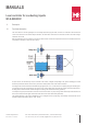
3.6
Construction of sensor
The sensor can be constructed in various ways:
In plastic containers, the electrodes can be tted in pairs on the container wall. Each pair always consists of a reference electrode and
a sensing electrode, which are placed at a distance of approx. 5-15 cm from each other. For liquids of high conductivity, just one elect-
rode at the bottom of the container is also good enough. The reference electrodes are connected together to the terminal COM. Due to
contamination deposits on the container walls with time, such constructions are probably not maintenance free. The wall area between
the electrodes should be periodically cleaned.
B+B Thermo-Technik GmbH | Heinrich-Hertz-Straße 4 | D-78166 Donaueschingen
Fon +49 771 8316-0 | Fax +49 771 831650 | info@bb-sensors.com | bb-sensors.com
9 / 11