
User manual


MANUALS
Technical changes reserved
0141 0316-112 05.2014
Level controller for conducting liquids
WLS-GEH230V
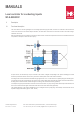
Electrodes of stainless steel rods, hanged from top into the medium, are ideally suited for this purpose. The reference electrode is in
the middle of the 4 diagonally arranged sensing electrodes which are placed in a span of approx. 1-5 cm. The spacing should be wide
enough so that no drop of liquid sticks back to the rods when the level falls down. These electrodes are practically maintenance free.
Cable probes are very simple to manufacture. For this purpose, multi-core silicon cable can be stripped at the end and joined to stainless
steel balls which act as weight and also contact surface. The individual weights are lowered in the container up to the desired switching
point and then the cable is tied up. For reference electrode, a bare stainless steel rope with weight can be used, which goes up to the
bottom of the container. Cable sensing elements are also very reliable and practically maintenance free.
For applications in condensate tubs and for low liquid levels, the sensing system can be constructed as a PCB which is mounted on the
tank wall. Such sensing elements should also be periodically cleaned if the medium is polluted.
3.7 Connection of external LEDs and pushbuttons
The connection of your own components shall be done at your own risk and is outside the guarantee coverage!
External LEDs or pushbuttons for switching the relays can be connected on the terminal strip at the lower edge of the PCB. A ready made
control unit for 12 / 24 V-model is available with us as accessories.
Pin Function Description
1, 2, 5, 6, 7, 8, 17, 18 NC unused
3 5V Stabilised operating voltage 5 V
4 15V Unstabilised operating voltage 15 V
9 LED SW R1 LED and Relay 2 switch, switching against GND, red LED against +15 V with Rv 4.7
k
10 LED SW R2 LED and Relay 2 switch, switching against GND, red LED to +15 V with Rv 4.7 k
11 LED 4 LED for level 4, LED green to +5 V with Rv 1 k
12 LED 3 LED for level 3, LED green to +5 V with Rv 1 k
13 LED 2 LED for level 2, LED green to +5 V with Rv 1 k
14 LED 1 LED for level 1, LED green to +5 V with Rv 1 k
15 LED EMPTY LED for level “Empty“, LED red to +5 V with Rv 1 k
16 GND Reference potential
B+B Thermo-Technik GmbH | Heinrich-Hertz-Straße 4 | D-78166 Donaueschingen
Fon +49 771 8316-0 | Fax +49 771 831650 | info@bb-sensors.com | bb-sensors.com
10 / 11