
User manual
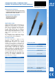

STAINLESS STEEL-TEMPERATURE PROBE
FOR SENSOR SWITCHING MODULE
Page 2 of 2
Released 09/2006 Rights reserved for change in technical data! HYGROSENS INSTRUMENTS GmbH Postfach 1054 D-79839 Löffingen Tel: +49 7654 808969-0 Fax: +49 7654 808969-9
Application notes
The continuous application temperature
should not exceed 80° C, because the
plastic connection cable can become
brittle and the insulation can be
defective. However, the temperature probe can be
used up to 100°C for short time. In cold condition
under -15°C, the cable should not be moved
otherwise cold breakage can appear.
For special applications or critical application
areas, the suitability of probe materials (housing
and cable) should be checked by the user before
installation.
The probe housing is electrically connected to
operating ground. Ground currents or balancing
currents are not allowed due to EMC reasons. In
case of unfavourable material combinations,
electro-corrosive effects are possible on contact
with water or other electrolytes.
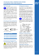
RJ12-plug connector configuration
The probe housing is connected to Pin 6. The
sensor is connected between Pin 5 and 4. and is
potential free. In case of Universal sensor-
switching module, Pin 5 is connected to the device
body and Pin 4 is input to measuring amplifiers.
For measuring probe, Pin 1,2 and 3 are not
occupied (in sensor-switching module these are
live terminals!)
Vie w of contacts on the plug
Pin Function Description
1,2,3 Unoccupied
4 SENS NTC sensor connection 2 (input)
5 GND NTC sensor connection 1 (GND)
6 SHLD Shielding and probe housing
Connection for Universal sensor
switching module (156503,-17,-30)
The applicable safety regulations
should be followed! Connection and
mounting operation should be carried
out by only trained personnel after switching off
the voltage The plug connector is brought out
through the hole in the housing and properly
secured through cable gland. The plug connector
of the probe is inserted at the right RJ12 socket
"ANALOG INPUT" (see sketch).
Configuration of jumpers
The operating mode for the temperature probe is
adjusted at the pin strip "ANA MODE". The
shorting jumpers are placed between position 2
and 5 of the pin strip.
The switching behaviour of the device is decided
by the jumper connections below the analog input
socket: In the right position, the relay switches ON
if the value of temperature exceeds the adjusted
switching point. In the left position, as shown in
sketch, the switching behaviour is reversed, i.e.
the relay switches ON if the temperature of the
probe goes below the adjusted switching point.
The switching behaviour of the device can be
observed at the light emitting diode (LED). In
active condition (= relay closed), the LED glows.
Since the three inputs of the module
are "OR" connected, the jumper
connections "Switching polarity" of the
two other unused inputs must be kept
in inactive position (see sketch). The associated
LEDs below the input socket may not glow. If this
is not ensured, the relay shall be always in ON
condition!
Adjustment of switching point
The adjustment of switching point for analog input
is done by a trim potentiometer "SETP ANA"
which is on the right edge of the PCB. The
adjustment is done through comparative
measurement at the desired switching point.
The adjustment range is right from approx. -40° C
(left end position of the potentiometer, i.e.
anticlockwise direction) up to approx. 100° C (right
end position). The middle position of the
potentiometers is at approx. 25°C.
The hysteresis (difference between ON and OFF
switching point) can be adjusted by the trim
potentiometer "HYS ANA". The setting is to be
done with a suitable screwdriver.
Adjustment of time delay
Finally, adjustment of time delay is carried out by
placing the jumper connection of the pin strip
"TIMER" at the desired position. With this, the
configuration is complete and the device is ready
for use.