
User manual

UNIVERSAL SENSOR SWITCHING MODULE
Instruction manual Page 8
Released 09/2006 Rights reserved for change in technical data! HYGROSENS INSTRUMENTS GmbH Postfach 1054 D-79839 Löffingen Tel: +49 7654 808969-0 Fax: +49 7654 808969-9
6 Technical appendix
6.1 General instructions
The technical appendix is useful for persons with adequate knowledge of electronics.
The applicable safety regulations shall be duly followed! Connection and mounting
work shall be carried out only after switching off the voltage supply.
The following instructions help in connection of your own probes at the input socket of
module. However, this certainly needs necessary attention, as different operating
voltages are present at the socket also. Sometimes, wrong connection may lead to
damage of the components or result in failure of the module itself.
In the following description, the three inputs have been explained separately as these
are also functionally independent of each other. Since the inputs are “OR” connected
before the time delay switch, the jumper plug "Switching polarity" of the other two
unused inputs must be plugged in the inactive position. The LEDs below the unused
input sockets may not glow.
Touching the electronic components in switched off condition is also to be avoided.
Electronic components can get damaged due to electrostatic discharge process. ESD
protection measures should be duly observed!
6.2 Switching input
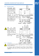
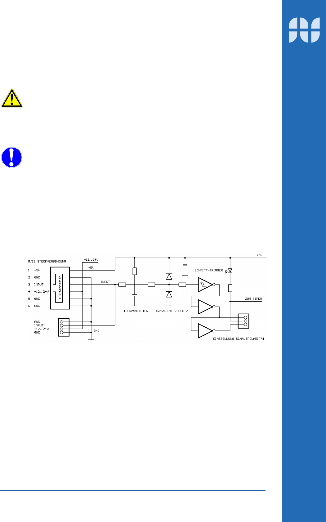
6.2.1 Circuit diagram
6.2.2 Functional description
The switching input is meant for connection of all switching sensors like REED-switch
or contacts. The contact is connected at the RJ12 plug connector from GND (pin 2,5
or 6) to INPUT (pin 3).
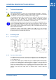
As soon as the contact opens, the input level goes to high through the internal pull-up
resistance. The Schmitt trigger is directed towards the high pass filter and transient
protection. The switching point of Schmitt-Trigger lies at approx. 1.5 V (low) and 3.5 V
(high). The switching polarity can be selected by the jumper connections at the output
of two series connected invertors. The signal triggers the internal timer, which in turn
switches on the relay at the output stage. The switching status of output is indicated
by LED.