
User manual


UNIVERSAL SENSOR SWITCHING MODULE
Instruction manual Page 6
Released 09/2006 Rights reserved for change in technical data! HYGROSENS INSTRUMENTS GmbH Postfach 1054 D-79839 Löffingen Tel: +49 7654 808969-0 Fax: +49 7654 808969-9
5 Assembly, adjustment and configuration
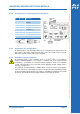
5.1 Electrical connection
5.1.1 Safety instructions
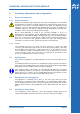
Caution ! Touching the high voltage parts may lead to fatal dangers. The mounting
and maintenance operations should be carried out by only trained personnel, who are
authorized on the basis of technical training in this field. The applicable safety
regulations are to be duly followed! The switching device must be assembled in a
switchgear cabinet or in a fully closed plastic housing. Mounting and servicing work
should be carried out only after switching off the voltage.
Due to wrong tightening of screws of the connection terminals or by use of
inappropriate tool, the terminals can get damaged because of which the insulation or
the contact can get disturbed. Badly connected leads can come out during operation
and cause a serious risk to safety. Due to contact resistance at terminal connections,
there can be increased heat generation which can cause fire. Wrongly wired
connections can destroy electric components and cause other damages.
5.1.2 Probes
The RJ12-plug connectors are meant for direct connection of probe. The plug
connector is brought out through the hole in the housing and is properly secured by
the PG7 gland. The connection of ready made probe is to be carried out as per
enclosed data sheet. While connecting the probes, care should be taken to use the
correct connection socket. The sockets are not coded and can get mixed up. The
probe can get damaged due to wrong connection.
5.2 Configuration
The connector configuration of ready made probe can be seen from the data sheet of
probe.
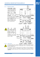
The switching behaviour of the device is decided by the jumper connections below the
input socket. The switching status of the device can be observed at the light emitting
diode(LED). In active condition (=Relay closed) the LED glows.
Since the three inputs of the module are connected through “OR” logic, the jumper
plugs "Switching polarity" of the other two unused inputs should be kept in unwired
inactive position (see sketch). The associated LEDs under the unused input sockets
will not glow. If this is not ensured, the relay will be always put on.
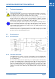
5.3 Adjustment of switching point
The adjustment of switching point is done as per probe type either by the trim
potentiometer for impedance input (“SETP IMP”) or for analog input (“SETP ANA”).
For the analog input, the hysteresis can also be adjusted at the potentiometer ("HYS
ANA"). Further instructions about adjustment can be obtained from the data sheet of
probe.
5.4 Adjustment of time delay
The configuration of time delay time is done by keeping the jumper plugs in the
terminal strip "TIMER" at the desired position. It must be set by only one bridge.