
User manual


UNIVERSAL SENSOR SWITCHING MODULE
Instruction manual Page 1
Released 09/2006 Rights reserved for change in technical data! HYGROSENS INSTRUMENTS GmbH Postfach 1054 D-79839 Löffingen Tel: +49 7654 808969-0 Fax: +49 7654 808969-9
Contents
1 General dangers and precautions .......................................................................................... 2
1.1 Instructions regarding documentation .............................................................................. 2
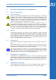
1.2 Safety instructions ............................................................................................................ 2
2 Description ............................................................................................................................. 3
2.1 Functional description....................................................................................................... 3
2.2 Range of available probes................................................................................................ 4
2.2.1 Dew formation probe (Condensate monitor) ...........................................................4
2.2.2 Humidity probe......................................................................................................... 4
2.2.3 Conductance probe ................................................................................................. 4
2.2.4 Temperature probe with protection tube..................................................................4
2.2.5 Temperature probe with screw threads ................................................................... 4
2.2.6 Light intensity probe................................................................................................. 4
3 Technical data ........................................................................................................................ 5
4 Ordering information............................................................................................................... 5
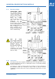
5 Assembly, adjustment and configuration ............................................................................... 6
5.1 Electrical connection......................................................................................................... 6
5.1.1 Safety instructions ................................................................................................... 6
5.1.2 Probes...................................................................................................................... 6
5.2 Configuration .................................................................................................................... 6
5.3 Adjustment of switching point ...........................................................................................6
5.4 Adjustment of time delay .................................................................................................. 6
5.4.1 Operating voltage .................................................................................................... 7
5.4.2 Load circuit............................................................................................................... 7
6 Technical appendix ................................................................................................................ 8
6.1 General instructions.......................................................................................................... 8
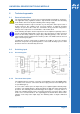
6.2 Switching input ................................................................................................................. 8
6.2.1 Circuit diagram......................................................................................................... 8
6.2.2 Functional description .............................................................................................. 8
6.2.3 Configuration of switching input socket (RJ12) .......................................................9
6.2.4 Adjustment and configuration .................................................................................. 9
6.2.5 Operating voltage connection .................................................................................. 9
6.3 Impedance input .............................................................................................................10
6.3.1 Circuit diagram.......................................................................................................10
6.3.2 Functional description ............................................................................................ 10
6.3.3 Configuration of input socket RJ12........................................................................ 11
6.3.4 Adjustment and configuration ................................................................................ 11
6.3.5 Operating voltage connection ................................................................................ 11
6.4 Analog input.................................................................................................................... 12
6.4.1 Circuit diagram.......................................................................................................12
6.4.2 Functional description ............................................................................................ 12
6.4.3 Configuration of analog input socket RJ12............................................................ 13
6.4.4 Adjustment and configuration ................................................................................ 13
6.4.5 Mode of operation ..................................................................................................14
6.4.6 Operating voltage connection ................................................................................ 14
6.5 Time delay switch...........................................................................................................15
6.5.1 Jumper connections...............................................................................................15
6.6 Relay...............................................................................................................................15
7 Guarantee ............................................................................................................................ 16
7.1 Repair and calibration service ........................................................................................ 16