
User manual

UNIVERSAL SENSOR SWITCHING MODULE
Instruction manual Page 13
Released 09/2006 Rights reserved for change in technical data! HYGROSENS INSTRUMENTS GmbH Postfach 1054 D-79839 Löffingen Tel: +49 7654 808969-0 Fax: +49 7654 808969-9
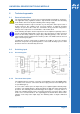
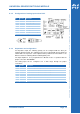
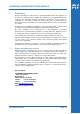
6.4.3 Configuration of analog input socket RJ12
Pin Function Description
1 +5V Operating voltage 5V
2 +12..24V Operating voltage 12..24V
3 NC Unoccupied
4 ANA INP Evaluation input
5 GND Device ground
6 GND Device ground/Shielding
View of contacts on the plug!
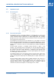
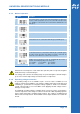
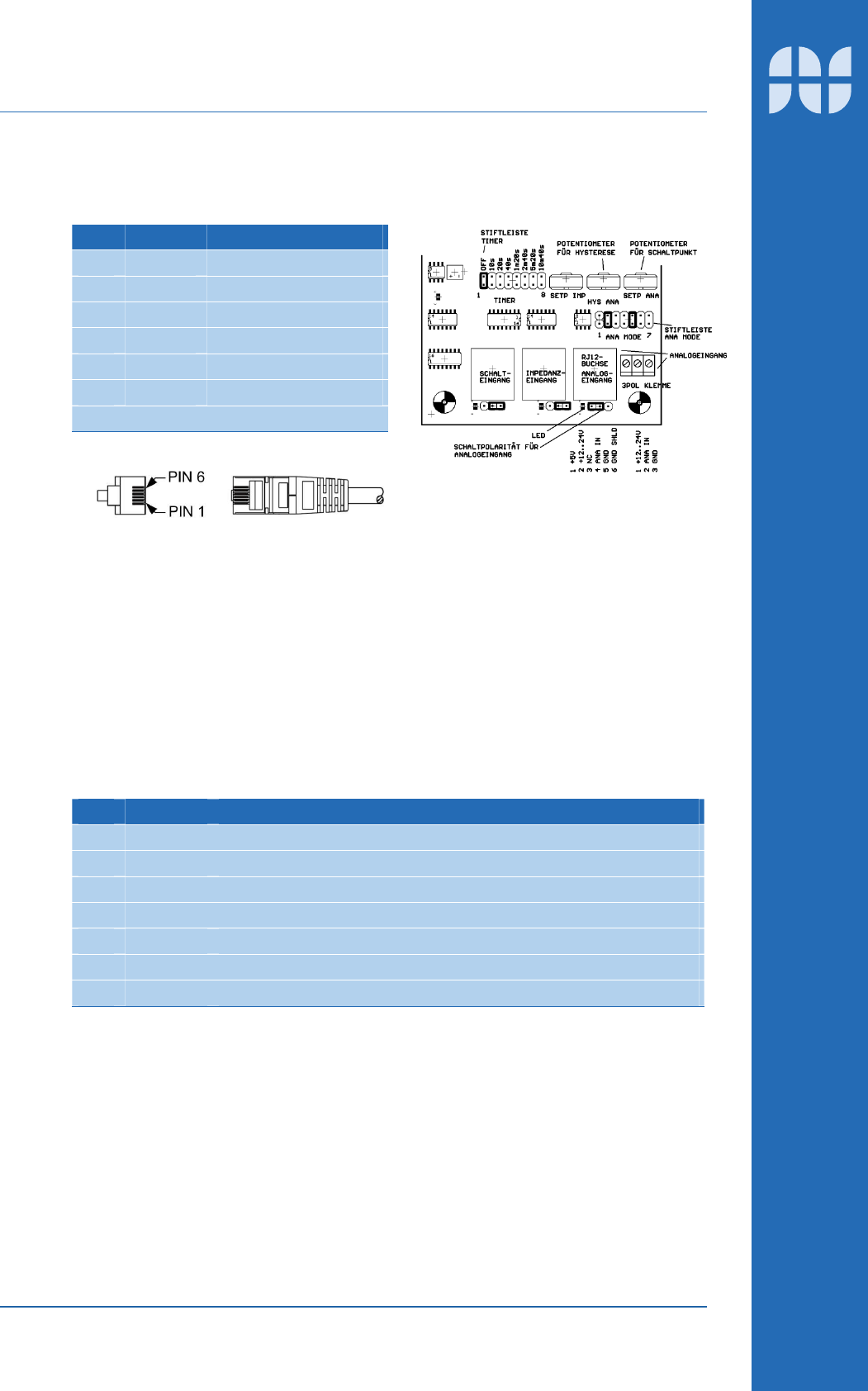
6.4.4 Adjustment and configuration
For impedance input, the switching polarity can be configured with the three pin
terminal strip below input. The switching point can be adjusted with the potentiometer
"SETP ANA". The hysteresis can be adjusted at the potentiometer "HYS ANA" i.e. the
difference between switching ON and switching OFF point.
The input amplifier is to be programmed for different modes of operation with the
jumper connection "ANA MODE":
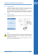
The analog input can be configured over a wide range through the jumper
connections:
Pin Function Description
1 PREAMP Increase the amplification by a factor of 1.6
2 RIN 100k Divider resistance for impedance measurement up to 100k
3 RIN 10k Divider resistance for impedance measurement up to 10k
4 RIN 1k Divider resistance for impedance measurement up to 1k
5 0..1V Bridging the input resistance for 0..1V or 0..20mA
6 0..10V Connection of a divider resistance for voltage input 0..10V
7 0..20mA Connection of a shunt for current measurement