
User manual

UNIVERSAL SENSOR SWITCHING MODULE
Instruction manual Page 9
Released 09/2006 Rights reserved for change in technical data! HYGROSENS INSTRUMENTS GmbH Postfach 1054 D-79839 Löffingen Tel: +49 7654 808969-0 Fax: +49 7654 808969-9
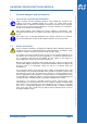
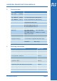
6.2.3 Configuration of switching input socket (RJ12)
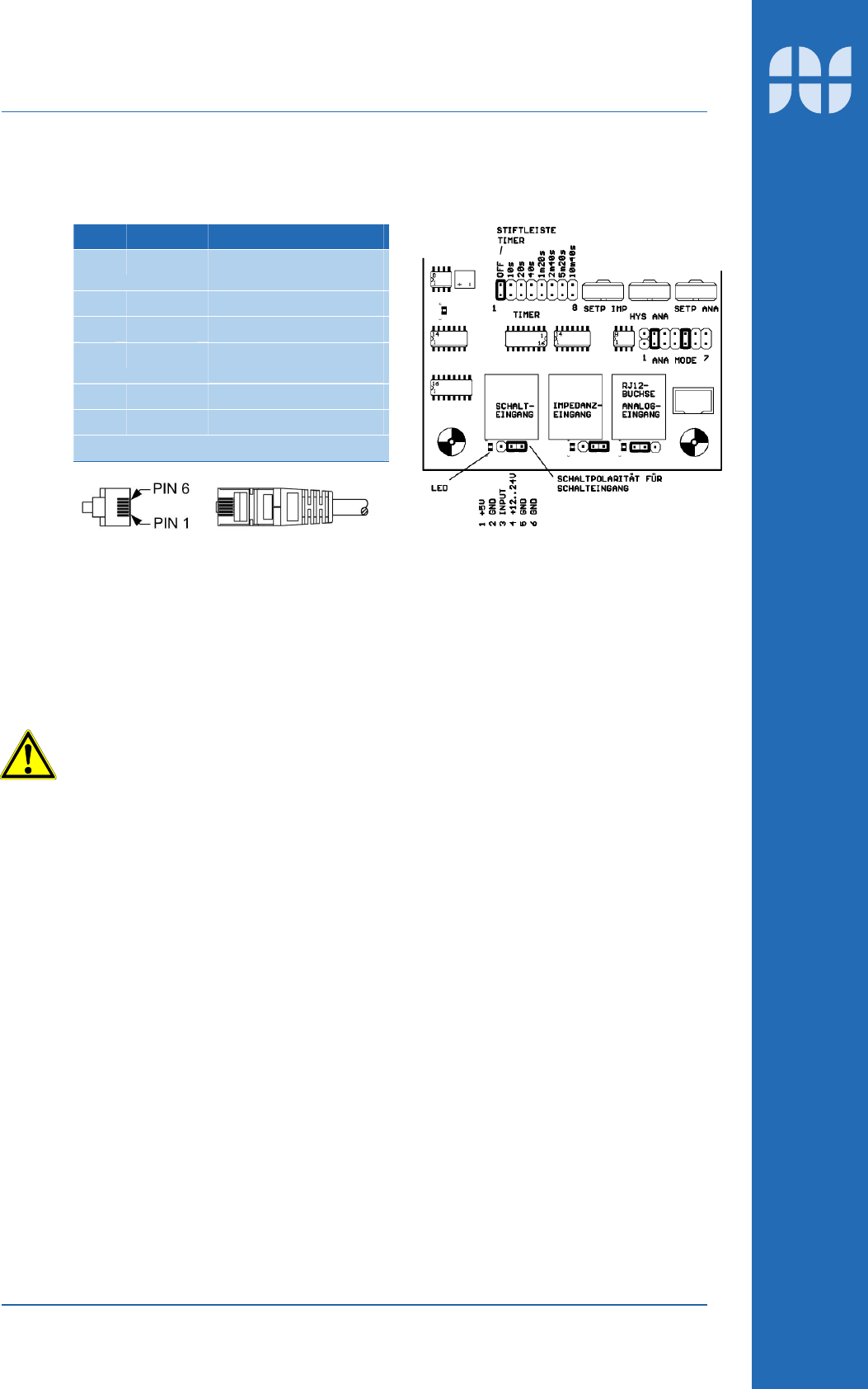
Pin Function Description
1 +5V Operating voltage 5V,
stabilized
2 GND Device ground
3 INPUT Input (Switch contact)
4 +12..24V Operating voltage 12...24V,
not stabilized
5 GND Device ground
6 GND Device ground
View of contacts on the plug!
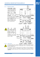
6.2.4 Adjustment and configuration
In switching input, only switching polarity can be configured. In the right position, the
NC contact of the relay is triggered. In the left position, the switch mode is reversed,
that means the NO contact of the relay is triggered.
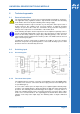
6.2.5 Operating voltage connection
An operating voltage of 5V is available at pin 1 of RJ12 socket to feed supply to
external switching amplifiers. The voltage is stabilised and short circuit protected
conforming to specification for integrated voltage regulators 78L05. The maximum
current output should not exceed 10 mA in total. Applying external voltage leads to
damage of components!
A rectified DC operating voltage is available at pin 4 of RJ12 socket to feed supply to
external components. This voltage is between 12V and 30 V DC depending upon the
model and supply voltage at input. The supply is unstabilised and without short circuit
protection. The maximum current output should not exceed 25 mA in total.