Ordering No. 15 65 03 CON-SENSW-12V Universal sensor switching module 12V OEM-Version without housing For industrial probes 0..1V, 0..10V, 0/4..20mA Direct connection of NTC, LDR, PTC Input with AC-evaluation (conductance) Adjustable Delay timer 10s..
3 4 5 6 7 Instruction manual Page 1 HYGROSENS INST RUMENT S GmbH Postfach 1054 2 General dangers and precautions .......................................................................................... 2 1.1 Instructions regarding documentation .............................................................................. 2 1.2 Safety instructions ............................................................................................................ 2 Description ..............................
1.1 Instructions regarding documentation Please carefully read the following instructions before putting into operation! The symbols used in the operating manual are to make you careful, before hand, regarding safety considerations and dangers. But all these symbols cannot substitute the text of the associated safety instructions in any way. Therefore, the instructions should also be always read completely! This symbol indicates likely danger for persons, material or environment.
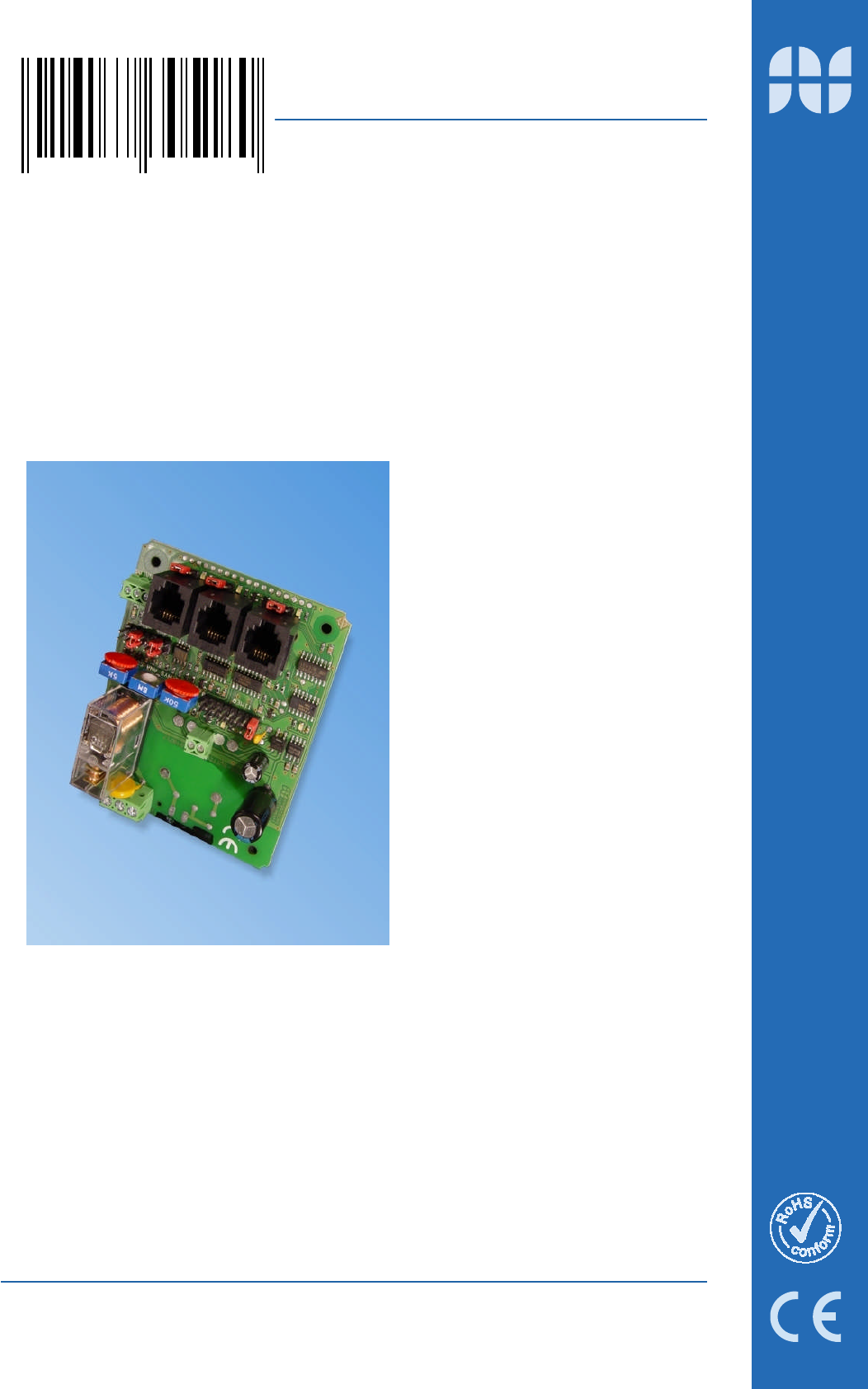
2.1 Functional description The universal sensor-switching module is suitable as a two-point regulator for a wide variety of sensors and industrial probes. A suitable sensor is connected at the input for sensing the parameter which is to be regulated. The relay mounted on the PCB gets triggered as per limit settings done through a potentiometer.
2.2.1 Dew formation probe (Condensate monitor) The dew formation probe can recognise upcoming dew formation before it originates. The sensing unit has two independent sensor elements for dew formation and condensation, which are integrated together and have such a reliable response pattern so that it can also sense already formed condensation. Typical application areas are humidity monitoring for kitchen, bathroom, showers and toilets, monitoring of external walls, cooling ducts and display windows.
UNIVERSAL SENSOR SWITCHING MODULE General Operating voltage Type –230V (156530) 230VAC/5 VA max. Operating voltage Type –MOD12V (156503) 12V..15V DC 65 mA max. 11V..14V AC 80 mA max. (without probe) Operating voltage Type –MOD24V (156517) 22V..28V DC 45 mA max. 15V..25 V AC 60 mA max.
Electrical connection 5.1.1 Safety instructions Caution ! Touching the high voltage parts may lead to fatal dangers. The mounting and maintenance operations should be carried out by only trained personnel, who are authorized on the basis of technical training in this field. The applicable safety regulations are to be duly followed! The switching device must be assembled in a switchgear cabinet or in a fully closed plastic housing.
UNIVERSAL SENSOR SWITCHING MODULE D-79839 Löffingen Tel: +49 7654 808969- 0 Fax: +49 7654 808969-9 Operating voltage HYGROSENS INST RUMENT S GmbH Postfach 1054 12V/24V-AC/DC Model: The operating voltage is connected at the terminals “SUPPLY VOLTAGE“. The rating of nominal voltage is mentioned on the PCB, under the voltage connection and also on the relay and must be maintained as per specifications on the data sheet in order to ensure an error free functioning.
6.1 General instructions The technical appendix is useful for persons with adequate knowledge of electronics. The applicable safety regulations shall be duly followed! Connection and mounting work shall be carried out only after switching off the voltage supply. The following instructions help in connection of your own probes at the input socket of module. However, this certainly needs necessary attention, as different operating voltages are present at the socket also.
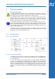
UNIVERSAL SENSOR SWITCHING MODULE Function Description 1 +5V Operating voltage 5V, stabilized 2 GND Device ground 3 INPUT Input (Switch contact) 4 +12..24V Operating voltage 12...24V, not stabilized 5 GND Device ground 6 GND Device ground View of contacts on the plug! 6.2.4 Adjustment and configuration In switching input, only switching polarity can be configured. In the right position, the NC contact of the relay is triggered.
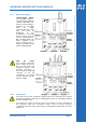
Circuit diagram 6.3.2 Functional description The impedance input is especially suitable for electrolytic type of sensors like conductance probes and level indicators, foam sensor, humidity and dew formation sensors, material moisture content probe or water/leakage probe. The operating principle is based on an AC voltage measurement that prevents the measuring current from creating electrochemical effects.
UNIVERSAL SENSOR SWITCHING MODULE Pin Function Description 1 +12..24V Operating voltage 12..24V 2 AC OUT AC output 3 CAP GND Capacitive ground 4 SENS IN Evaluation input 5 CAP GND Capacitive ground 6 GND Device ground D-79839 Löffingen Tel: +49 7654 808969- 0 Fax: +49 7654 808969-9 Configuration of input socket RJ12 View of contacts on the plug! 6.3.
6.4.1 Circuit diagram 6.4.2 Functional description The analog input is to be adapted over a pin contact strip for various types of sensors and industrial probes. In order to also use resistive sensors as probes, there is possibility of applying the reference voltage to the sensor through a configurable preset resistor, which works as a voltage divider. The signal is first pre-amplified and then evaluated with a comparator.
UNIVERSAL SENSOR SWITCHING MODULE Pin Function Description 1 +5V Operating voltage 5V 2 +12..24V Operating voltage 12..24V 3 NC Unoccupied 4 ANA INP Evaluation input 5 GND Device ground 6 GND Device ground/Shielding D-79839 Löffingen Tel: +49 7654 808969- 0 Fax: +49 7654 808969-9 Configuration of analog input socket RJ12 View of contacts on the plug! 6.4.
1 Description Impedance input 100 k: All such components are suitable as sensors in which the resistance value is a function of the measured parameter e.g. LDRs (photo resistors) or NTCs (temperature sensors). The sensor with a resistance value of 0 ..100kOhm is connected at the RJ12 socket between ANA INP (pin 3) and GND (pin 2). Same as (1), however for sensors with resistance value of 0..10k 2 Same as (1), however for sensors with resistance value of 0..1k 3 4 Voltage input 0..
Time delay switch A digital time delay switch is integrated in the module, which can be adjusted over a wide range. The applications are many, for example, for direct triggering of cooling units or pumps, in order to avoid short time running time of the units. The time delay switch ensures that the load remains switched on for a certain extra time period even after the switching criterion is not fulfilled further.
UNIVERSAL SENSOR SWITCHING MODULE Hearty congratulations on the purchase of this high quality product! The quality of our products is constantly monitored within the framework of our Quality Management systems as per ISO 9001 standards. Nevertheless, if still there are any reasons for complaint, we are ready to rectify the shortcomings free of charge within the guarantee period of 24 months, if it is evident that the defect is due to some mistake on our part.
79843 Löffingen, Germany The technical information in this document has been checked with adequate care at our end and is intended to inform about the product and its applications. The descriptions are not to be understood as assurance of the defined characteristics of the product and should be checked by the user for the intended application. Any possible industrial third party patent rights are to be considered. Issued September 2006 - This documentation supersedes all previous editions.