Model ES1AWB 802.11b Wireless Serial Server Manual Documentation Number: ES1AWB-2907m pn6908-rev003 B&B Electronics Mfg Co Inc – 707 Dayton Rd - PO Box 1040 - Ottawa IL 61350 - Ph 815-433-5100 - Fax 815-433-5104 – www.bb-elec.com B&B Electronics Ltd – Westlink Commercial Park – Oranmore, Galway, Ireland – Ph +353 91-792444 – Fax +353 91-792445 – www.bb-europe.
Manual Documentation Number: ES1AWB-2907m pn6908-rev003 B&B Electronics Mfg Co Inc – 707 Dayton Rd - PO Box 1040 - Ottawa IL 61350 - Ph 815-433-5100 - Fax 815-433-5104 – www.bb-elec.com B&B Electronics Ltd – Westlink Commercial Park – Oranmore, Galway, Ireland – Ph +353 91-792444 – Fax +353 91-792445 – www.bb-europe.
International Headquarters B&B Electronics Mfg. Co. Inc. 707 Dayton Road Ottawa, IL 61350 USA Phone (815) 433-5100 -- General Fax (815) 433-5105 Website: www.bb-elec.com Sales e-mail: orders@bb-elec.com -- Fax (815) 433-5109 Technical Support e-mail: support@bb.elec.com -- Fax (815) 433-5104 European Headquarters B&B Electronics Ltd. Westlink Commercial Park Oranmore, Co. Galway, Ireland Phone +353 91-792444 -- Fax +353 91-792445 Website: www.bb-europe.com Sales e-mail: sales@bb-europe.
© 2005 B&B Electronics. No part of this publication may be reproduced or transmitted in any form or by any means, electronic or mechanical, including photography, recording, or any information storage and retrieval system without written consent. Information in this manual is subject to change without notice, and does not represent a commitment on the part of B&B Electronics.
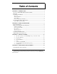
Table of Contents CHAPTER 1: INTRODUCTION............................................................................. 1 ABOUT YOUR ES1AWB WIRELESS SERIAL SERVER ................................................. 1 FEATURES .................................................................................................................. 1 COMMUNICATION MODES ......................................................................................... 1 Direct IP ..................................................
CHAPTER 5: USING THE WEB CONFIGURATION AND MANAGEMENT INTERFACE............................................................................................................. 14 LOGGING IN ............................................................................................................. 14 LOGGING OUT ......................................................................................................... 14 USING TUTORIAL AND HELP ...................................................................
Serial................................................................................................................... 33 Network............................................................................................................... 34 REBOOT ................................................................................................................... 35 CHAPTER 8: USING REALPORT....................................................................... 36 Configuring the IP Address.............
Manual Documentation Number: ES1AWB-2907m pn6908-rev003 B&B Electronics Mfg Co Inc – 707 Dayton Rd - PO Box 1040 - Ottawa IL 61350 - Ph 815-433-5100 - Fax 815-433-5104 – www.bb-elec.com B&B Electronics Ltd – Westlink Commercial Park – Oranmore, Galway, Ireland – Ph +353 91-792444 – Fax +353 91-792445 – www.bb-europe.
Introduction Chapter 1: Introduction Thank you for purchasing an ES1AWB Wireless Serial Server. Like all B&B Electronics products, your serial server has been manufactured to high standards of quality and performance to ensure your complete satisfaction. Please read this manual and carefully follow the instructions to achieve best results. For additional information on this and other products and for technical support, contact B&B Electronics.
Introduction • Software Support - Windows 98/ME/2000/XP/NT 4.0 or Vista • Firmware upload for future revisions/upgrades • Small compact case • LEDs indicate link integrity and data transfer activity • Web Configuration and Management user interface • Email event notification Communication Modes ES1AWB Wireless Serial Servers allow you to connect serial devices over a wireless network. The connection can be configured in several modes.
Introduction Paired Mode Paired Mode (also called Serial Tunneling or Serial Bridge mode) allows serial devices connected to two ES1AWB serial servers to communicate across a network. The two ES1AWB serial servers automatically connect to each other. In Paired Mode the heartbeat feature ensures reliable communications by restoring the connection if communications are temporarily lost at either end due to loss of power or Ethernet connection.
Introduction The enabling technology for ES1AWB wireless serial servers is based on the IEEE 802 standard. Some background on the standard follows. 802.11 Wireless Networking IEEE 802.11 is a set of standards that defines how multiple devices can communicate on a wireless network. The standard has grown into a set of several standards that define various features and functions. The 802.11b standard defines the physical and data link layers for a wireless network using the 2.
Introduction IEEE 802.11b IEEE 802.11b standard specifies a WLAN that operates on the 2.4 GHz band at data rates up to 11 Mbps. Equipment that conforms to the 802.11b standard can interoperate with equipment conforming to faster (up to 54 Mbps) 802.11g equipment and they will interoperate. However, when connected into the same network the 802.11g equipment will operate at the 11 Mbps limitation of the 802.11b equipment. For media access, 802.
Introduction Manual Documentation Number: ES1AWB-2907m pn6908-rev003 B&B Electronics Mfg Co Inc – 707 Dayton Rd - PO Box 1040 - Ottawa IL 61350 - Ph 815-433-5100 - Fax 815-433-5104 – www.bb-elec.com B&B Electronics Ltd – Westlink Commercial Park – Oranmore, Galway, Ireland – Ph +353 91-792444 – Fax +353 91-792445 – www.bb-europe.
Hardware Overview Chapter 2: Hardware Overview Package Checklist ES1AWB Wireless Serial Servers are shipped with the following items included: 9 9 9 9 The ES1AWB module A printed version of this user manual A printed version of the ES1AWB Quick Start Guide CD-ROM disc with o B&B discovery software o RealPort drivers for Windows 98/ME/2000/XP/ NT 4.0 /Vista o This manual in PDF format o The ES1AWB Quick Start Guide in PDF format Figure 1.
Hardware Overview Indicators, Switches and Connectors Link Integrity LED • When the yellow LED is illuminated it indicates that a connection (link integrity) has been established between the serial server and an access point. • If this LED is blinking slowly the ES1AWB is in ad hoc mode. • If this LED is blinking quickly the ES1AWB is scanning for a network. Network Activity LED When the green LED is flashing it indicates data is being sent across the network.
Hardware Overview Connecting the Hardware A typical connection for the ES1AWB Wireless Serial Server is infrastructure mode operation, in which the ES1AWB communicates with a PC on a wired network via an access point, which is often a wireless switch or router. Figure 2. Connection via the Wireless LAN Manual Documentation Number: ES1AWB-2907m pn6908-rev003 B&B Electronics Mfg Co Inc – 707 Dayton Rd - PO Box 1040 - Ottawa IL 61350 - Ph 815-433-5100 - Fax 815-433-5104 – www.bb-elec.
Hardware Overview Other Hardware Connections The ES1AWB Wireless Serial Server also can communicate directly with a PC equipped with a wireless card (in ad hoc mode). Figure 3. Wireless Ad Hoc Connection In Serial Tunneling mode two serial devices can communicate via two ES1AWB Wireless Serial Servers. Figure 4. Serial Tunneling Ad Hoc Connection Serial tunneling also can occur between two ES1AWB serial servers communicating with individual access points and across a wired network. Figure 5.
Getting Started Chapter 3: Getting Started 1. Check the contents of your ES1AWB package. It should contain… The ES1AWB module with SMA antenna A 5VDC power supply A printed version of this user manual A printed version of the ES1AWB Quick Start Guide CD-ROM disc with discovery software, RealPort software, this manual and Quick Start guide 2.
Getting Started If you are configuring your own access point (a wireless switch or router) ensure that it is configured as a DHCP server with the Wireless Network Name (SSID): Connect 4. Get the IP Address Use the discovery software on your CD (finder.exe) to get the IP address for your ES1AWB 5. Login In a web browser on your PC, type in the IP address and access the Web Configuration and Management Interface Login using the username ‘root’ and password ‘dbps’ 6.
Configuring the ES1AWB Chapter 4: Configuring the IP Address Before you can begin the configuration of your ES1AWB you must know its IP address to access it with a web browser. Once you have access to the Configuration and Management Interface via a web browser you can reset the IP address using static IP addressing, if necessary. Your ES1AWB comes from the factory configured to obtain an IP address dynamically, or failing that, to generate its own IP address using the APIPA protocol.
Configuring the IP Address Identify your ES1AWB by its MAC address (printed on a label on the ES1AWB). If you need to change the IP address of the ES1AWB, you can accomplish this using the Discovery software, or you can open the Web Configuration and Management Interface and do it there. (See Configuring Network Settings later in the next chapter.) 1. To change the IP address of the ES1AWB from the discovery software, click Configure IP Settings. 2.
Using the Web Configuration and Management Interface Chapter 5: Using the Web Configuration and Management Interface The ES1AWB Serial Server can be configured using the Configuration and Management Interface via a standard web browser such as Internet Explorer or Firefox. Logging In 1. Before you can begin configuring your ES1AWB Serial server, you must login to the Configuration and Management Interface.
Using the Web Configuration and Management Interface Using Tutorial and Help You can access the ES1AWB Tutorial by clicking Tutorial on the Configuration and Management homepage. Clicking Help on any page of the Configuration and Management Interface opens topics specific to that page. After logging in, if there is no activity for a period of time your session may time out. Clicking on any link will return you to the Web Login page where you will have to log in again to continue your session. Figure 7.
Using the Web Configuration and Management Interface Figure 8. Network Configuration, IP Settings Page IP Settings The IP Settings section allows you to select between dynamic or static IP addressing. The ES1AWB’s default setting is Obtain an IP address automatically using DHCP, or dynamic IP addressing. When the ES1AWB is first connected it will try to obtain an IP address automatically. If it fails, it will assign an IP address to itself using the Automatic Private IP Addressing (APIPA) protocol.
Using the Web Configuration and Management Interface server to connect to and associate with a specific network. If the network name is left blank the serial server will connect to the first available network. Figure 9.
Using the Web Configuration and Management Interface Wireless Security Settings The Wireless Security Settings section is divided into several subsections including: • Network Authentication • Data Encryption • WEP Keys • WPA PSK • Username/Password Multiple options can be accessed under each security-related area. For Network Authentication and Data Encryption selecting Any enables all methods and the actual method used will depend on the capabilities of the wireless network.
Using the Web Configuration and Management Interface Configuring the Serial Port The Serial Port Configuration page displays information about the serial port on your ES1AWB, including its description, its profile (operating mode) and serial settings (baud rate, data bits, parity, stop bits). You will have to configure these parameters to set up your system for the type of operation required and to match the parameters of the serial device to which the ES1AWB is connected.
Using the Web Configuration and Management Interface Figure 10. Select Port Profile Page RealPort Select RealPort to implement the use of virtual COM ports. This allows you to map a COM port on a PC to the serial port on your ES1AWB. Using RealPort software (included with the ES1AWB) you create a virtual COM port on the PC. When your application sends data to this port, RealPort redirects the data across the network to the ES1AWB.
Using the Web Configuration and Management Interface TCP Sockets Select TCP Sockets to implement Direct IP Mode using TCP. When using TCP Sockets your serial server can be configured as a TCP server or TCP client. TCP Server Settings If your ES1AWB is configured as a TCP server, other network devices can initiate a TCP connection with the serial device connected to the ES1AWB serial port. (This is also referred to as reverse telnet.
Using the Web Configuration and Management Interface Figure 12. TCP Client Settings Consult the Tutorial and online Help for more detail. UDP Sockets Select UDP Sockets to implement Direct IP Mode using UDP protocol. When using UDP Sockets your serial server can be configured as a UDP server or UDP client. UDP Server Settings If your ES1AWB is configured as a UDP server, other network devices can initiate a UDP connection with the serial device connected to the ES1AWB serial port.
Using the Web Configuration and Management Interface Figure 13. UDP Server Settings UDP Client Settings If your ES1AWB is configured as a UDP client you can automatically distribute serial data from you ES1AWB to many devices at the same time. This is sometimes referred to as Data Distribution or UDP Multicast. Figure 14. UDP Client Settings You can configure multiple destinations. In the appropriate boxes, type the Description, Send To IP address or DNS name and UDP Port number, then click Add.
Using the Web Configuration and Management Interface Serial Bridge Select Serial Bridge to implement Paired Mode (also called serial tunneling). This allows serial devices connected to two ES1AWB serial servers to communicate across the network. The two ES1AWB serial servers automatically connect to each other. Modem Emulation Select Modem Emulation to configure the serial port to operate as if it is a modem.
Using the Web Configuration and Management Interface Configuring Alarms and Notification The ES1AWB can be configured to generate alarms and send notification emails based on the occurrence of specific events. Events include the states of some RS-232 handshake (GPIO) lines and the detection of specified character patterns within the serial data stream. The Alarms Configuration page displays the current alarm settings and allows you to configure them.
Using the Web Configuration and Management Interface Alarm Destinations Alarm Destinations allows you to specify where to send alarm notification emails, their priority and subject title. Type the information into the Mail to email address, CC address, set the Priority and type in the Subject line. To send an SNMP trap, select Send SNMP trap to following destination when alarm occurs and type the destination IP address for the SNMP trap.
Using the Web Configuration and Management Interface Manual Documentation Number: ES1AWB-2907m pn6908-rev003 B&B Electronics Mfg Co Inc – 707 Dayton Rd - PO Box 1040 - Ottawa IL 61350 - Ph 815-433-5100 - Fax 815-433-5104 – www.bb-elec.com B&B Electronics Ltd – Westlink Commercial Park – Oranmore, Galway, Ireland – Ph +353 91-792444 – Fax +353 91-792445 – www.bb-europe.
Managing the ES1AWB Chapter 6: Managing the ES1AWB System Settings The System configuration page contains two sections: the Device Identity Settings and the Simple Network Management Protocol (SNMP) Settings. Device Identity Settings The Device Identity Settings page allows you to enter a Description such as the network name of the ES1AWB, the SNMP Contact person, a text description of the Location of the ES1AWB and the Device ID number.
Managing the ES1AWB Changing the Root Username and Password You may want to change the Root username and password after you have gained access to the Web Configuration and Management Interface. To change your username and password click Users under the Configuration menu. Follow the prompts to enter a new username and password. Click Apply to complete the procedure.
Managing the ES1AWB 3. Click the User Access link. The User Access page opens. Select Allow command line access and/or Web Interface Access. Click Apply. (See the online help for more information on these choices.) 4. Click the User Permissions link. The User Permissions page appears containing a list of permissions and dropdown lists. For each item on the list select the level of permission to be granted to the user. (See the online help for more information on these choices.
Managing the ES1AWB Manual Documentation Number: ES1AWB-2907m pn6908-rev003 B&B Electronics Mfg Co Inc – 707 Dayton Rd - PO Box 1040 - Ottawa IL 61350 - Ph 815-433-5100 - Fax 815-433-5104 – www.bb-elec.com B&B Electronics Ltd – Westlink Commercial Park – Oranmore, Galway, Ireland – Ph +353 91-792444 – Fax +353 91-792445 – www.bb-europe.
Using Administrative Features Chapter 7: Using Administrative Features For additional information on each of the following features access the Tutorial and Help files. File Management The File Management page provides facilities to upload and/or manage custom web pages and files such as your applet and HTML files to the ES1AWB. Uploading an index.htm or index.html file will automatically load that page upon logging into the ES1AWB.
Using Administrative Features System Information The System Information page displays information about your ES1AWB: General • Model • MAC Address • Firmware Version • Boot Version • POST Version • CPU Utilization • Up Time • Total Memory • Used Memory • Free Memory GPIO Not applicable to the ES1AWB Serial The Serial page displays a table containing the following information: • Port number • Description • Profile • Serial Configuration (baud rate, data bits, parity, stop bits
Using Administrative Features Figure 15. Serial Port Diagnostics Page Network The Network page displays statistics related to IP, TCP, UDP and ICMP protocol activities. Figure 16. Network Information Page Manual Documentation Number: ES1AWB-2907m pn6908-rev003 B&B Electronics Mfg Co Inc – 707 Dayton Rd - PO Box 1040 - Ottawa IL 61350 - Ph 815-433-5100 - Fax 815-433-5104 – www.bb-elec.
Using Administrative Features Reboot The Reboot page allows you to reboot the ES1AWB. If you click on Reboot the process will take approximately one minute to complete. Manual Documentation Number: ES1AWB-2907m pn6908-rev003 B&B Electronics Mfg Co Inc – 707 Dayton Rd - PO Box 1040 - Ottawa IL 61350 - Ph 815-433-5100 - Fax 815-433-5104 – www.bb-elec.com B&B Electronics Ltd – Westlink Commercial Park – Oranmore, Galway, Ireland – Ph +353 91-792444 – Fax +353 91-792445 – www.bb-europe.
Using RealPort Chapter 8: Using RealPort RealPort is a COM port redirector program that allows you to add and remove virtual COM ports on your PC and update the RealPort software. Virtual COM ports allow you to set up a connection between your PC and the device connected to the serial port on your ES1AWB via an Ethernet network connection using TCP/IP. If you will be using virtual COM ports (configuring your serial port with the RealPort profile) you must use RealPort to configure those ports on your PC.
Using RealPort Adding a Virtual COM Port using RealPort Windows 2000/XP/Vista: 1. Locate the RealPort driver software on the CD you received with your ES1AWB. 2. Find the RealPort setup.exe file for your PC’s operating system. 3. Start the setup.exe file. The RealPort Setup Wizard Welcome dialog appears. 4. Select the Add a New Device, then click Next. The Select Device dialog appears listing the IP Address, MAC Address and Model of all devices on the network.
Using RealPort 4. Select the Remove an Existing Device, then click Next. The Select Device to Remove dialog appears listing the IP Address, MAC Address and Model of all devices on the network. To identify your ES1AWB compare the MAC address listed with the MAC address on the label on your ES1AWB. 5. Select the device to be removed and click Next. 6. In the Select COM Port dialog that appears, select the COM port number to be assigned to the ES1AWB. Click Next. A progress screen will appear. 7.
Using RealPort Manual Documentation Number: ES1AWB-2907m pn6908-rev003 B&B Electronics Mfg Co Inc – 707 Dayton Rd - PO Box 1040 - Ottawa IL 61350 - Ph 815-433-5100 - Fax 815-433-5104 – www.bb-elec.com B&B Electronics Ltd – Westlink Commercial Park – Oranmore, Galway, Ireland – Ph +353 91-792444 – Fax +353 91-792445 – www.bb-europe.
Default Configuration Settings Appendix A: Default Configuration Settings Server Name ES1AWB Username: root Password: dbps DHCP: Enabled Baud Rate: 9600 Data//Stop: 8-1 Parity: None Flow Control: None TCP/UDP Protocol: TCP Connection Mode: TCP Socket TCP/UDP port: 2001 Manual Documentation Number: ES1AWB-2907m pn6908-rev003 B&B Electronics Mfg Co Inc – 707 Dayton Rd - PO Box 1040 - Ottawa IL 61350 - Ph 815-433-5100 - Fax 815-433-5104 – www.bb-elec.
Default Configuration Settings Manual Documentation Number: ES1AWB-2907m pn6908-rev003 B&B Electronics Mfg Co Inc – 707 Dayton Rd - PO Box 1040 - Ottawa IL 61350 - Ph 815-433-5100 - Fax 815-433-5104 – www.bb-elec.com B&B Electronics Ltd – Westlink Commercial Park – Oranmore, Galway, Ireland – Ph +353 91-792444 – Fax +353 91-792445 – www.bb-europe.
Product Specifications Appendix B: Product Specifications Model: Manual: CD-ROM disk: Operating Systems Supported: Dimensions Power Supply Requirements: Power Consumption: Operating Temperature: Storage Temperature: ES1AWB Paper copy of this manual, PDF available RealPort virtual COM port software for Windows 98/ME/2000/XP/NT 4.0/ Vista B&B discovery software (finder.exe) PDF of ES1AWB User Manual PDF of Quick Start guide Windows 98/ME/2000/XP/NT 4.
Product Specifications Serial Connector: RS-232 Interface Lines Supported: Serial Data Rates: Parity: 9 pin D-type male (DB-9M) TD, RD, RTS, CTS, DTR, DSR, DCD, DSR, GND 50, 75, 110, 134, 150, 200, 300, 600, 1200, 1800, 2400, 4800, 9600, 14400, 19200, 28800, 38400, 57600, 115200, 230400 bps None, Even, Odd, Mark, Space Data Bits: 5, 6, 7 or 8 Stop Bits: 1 or 2 Flow control: Set-up Options: Configuration Modes: Configuration Method: Security: Device Management: IP Address Assignment: TCP/UDP Forwardi
Dimensional Diagrams Appendix C: ES1AWB Dimensional Diagram Figure 17. Dimensional Diagram of the ES1AWB Manual Documentation Number: ES1AWB-2907m pn6908-rev003 B&B Electronics Mfg Co Inc – 707 Dayton Rd - PO Box 1040 - Ottawa IL 61350 - Ph 815-433-5100 - Fax 815-433-5104 – www.bb-elec.com B&B Electronics Ltd – Westlink Commercial Park – Oranmore, Galway, Ireland – Ph +353 91-792444 – Fax +353 91-792445 – www.bb-europe.
Dimensional Diagrams Manual Documentation Number: ES1AWB-2907m pn6908-rev003 B&B Electronics Mfg Co Inc – 707 Dayton Rd - PO Box 1040 - Ottawa IL 61350 - Ph 815-433-5100 - Fax 815-433-5104 – www.bb-elec.com B&B Electronics Ltd – Westlink Commercial Park – Oranmore, Galway, Ireland – Ph +353 91-792444 – Fax +353 91-792445 – www.bb-europe.
Appendix D: RS-232 Connections DB-9M RS-232 RS-232 Pin Signal Designation DTE 1 Carrier Detect DCD In 2 Receive Data RXD In 3 Transmit Data TXD Out 4 Data Terminal Ready DTR Out 5 Signal Ground GND --- 6 Data Set Ready DSR In 7 Request To Send RTS Out 8 Clear To Send CTS In 9 Not connected NA NA Figure 18. RS-232 Connections in a DB-9 Connector DECLARATION OF CONFORMITY Manufacturer’s Name: Manufacturer’s Address: B&B Electronics Manufacturing Company P.O.