
User`s guide

43
●
●
●
●
●
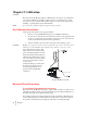
Chapter 4
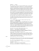
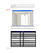
Word Offset Description
RATESETPOINT 11 Total . (MSW)
STATE
12
State
VERSION
13
Firmware version
STATUS 14 Statusword (See Statusword below)
COUNTER
15
Statusword
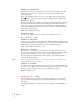
At word 14, the module returns a binary statusword where each bit indicates a state or
condition within the module. To interpret these states, note which bits are ON and use the
chart below to match each bit location to the state it represents.
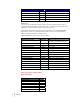
For Example: If the statusword is 69 (45 hex) with a binary value of 0000 0000 0100
0101, bits 0, 2, and 6 are on. Bit 0 indicates an A/D conversion error, bit 2 indicates
status is ON and bit 6 indicates a shutdown error.
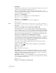
STATUSWORD bit positions refer to these variables:
Word # Definition
ERRORADCONVERT 0x0001/0
Millivolt return from the load cell
system is out of range for the unit.
ERRORADFAILURE 0x0002/1 Unit’s A/D converter not responding.
STATUS_ON 0x0004/2 System on or off
ERRORLOWALARM 0x0008/3 Low alarm
ERRORHIGHALARM 0x0010/4 High alarm
ERRORCONTROL_LOST 0x0020/5 Controller communication failure
ERROR_SHUTDOWN 0x0040/6 Shutdown
ERROR_RANGE 0x0080/7 Out of range value
ERROR_REC 0x0100/8 REC value over high limit
ERROR_RECMINUS 0x0200/9 REC value below low limit
ERROR_REFILL_OVER 0x0400/10 Exceed refill limit
STATUS_REFILL 0x0800/11 Refill process active
STATUS_BATCH_COMPLETE 0x1000/12 Batch process completed
ERROREEPROMWRITE 0x4000/14 EEPROM Hardware Error
STATUSCHANENABLED 0x8000/15 Set if channel is enabled
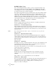
States (Word 12 of input table)
Mode (state) Table
Mode Value
IDLE_MODE 0
AUTO_MODE 1
MANUAL_MODE 2
START_MODE 3
STOP_MODE 4
SHUT_OFFMODE 5
PAUSE_MODE 6