
User`s guide

8
●
●
●
●
●
Chapter 3
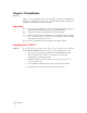
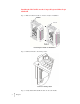
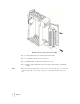
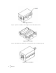
Step 4: When you have the modules aligned, press Lever B towards module A to fasten
the connector to Module A.
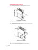
Connector in locked position
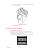
Step 5. The installation is complete.
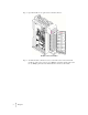
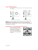
Installing the I/O Connector Diagrams
About the Module I/O Connector
The I/O Connector at the front of the module connects the module to the Remote
Terminal (RTA), a load sensor, or the HI 2151T series junction box depending on how
many load sensors are installed in the weigh system.
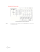
The pin-out diagram is shown below and can be located on the inside of the module door.
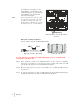
Single Channel
Pin 1 Sheild1
Pin 3 C2-1 Violet
Pin 5 C2+1 Gray
Pin 7 Exc-1 Black
Pin 9 Sen-1 Brown
Pin 11 Sig-1 White
Pin 13 Sig+1 Green
Pin 15 Sen+1 Blue
Pin 17 Exc+1 Red
Module connector pin-out diagram