
User manual


RS-422 Connections
Manual Documentation Number: ESP901-902_4105m Appendix B 75
B&B Electronics Mfg Co Inc – 707 Dayton Rd - PO Box 1040 - Ottawa IL 61350 - Ph 815-433-5100 - Fax 815-433-5104 – www.bb-elec.com
B&B Electronics Ltd – Westlink Commercial Pk – Oranmore, Galway, Ireland – Ph +353 91-792444 – Fax +353 91-792445 – www.bb-europe.com
A
A
P
P
P
P
E
E
N
N
D
D
I
I
X
X
B
B
:
:
R
R
S
S
-
-
4
4
2
2
2
2
C
C
O
O
N
N
N
N
E
E
C
C
T
T
I
I
O
O
N
N
S
S
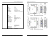
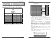
Serial Server DB-9 Pin-outs in RS-422 Mode
RS-422
Signal Name
Direction
RS-422
DB9M
Pin
Receive Data A (−) In RXDA (−) 1
Receive Data B (+) In RXDB (+) 2
Transmit Data B (+) Out TXDB (+) 3
Transmit Data A (−) Out TXDA (−) 4
Signal Ground --- GND 5
Clear to Send A (−) In CTSA (−) 6
Clear to Send B (+) In CTSB (+) 7
Request to Send B (+) Out RTSB (+) 8
Request to Send A (−) Out RTSA (−) 9
Figure 66. RS-422 Connections in a DB-9 Connector
RS-422 Connections
76 Appendix B Manual Documentation Number: ESP901-902_4105m
B&B Electronics Mfg Co Inc – 707 Dayton Rd - PO Box 1040 - Ottawa IL 61350 - Ph 815-433-5100 - Fax 815-433-5104 – www.bb-elec.com
B&B Electronics Ltd – Westlink Commercial Pk – Oranmore, Galway, Ireland – Ph +353 91-792444 – Fax +353 91-792445 – www.bb-europe.com
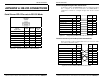
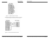
Figure 67. RS-422 Connections with Flow Control
In the RS-422 mode, TXD lines are outputs and RXD lines are inputs.
Connect the
Serial Server TXDB(+) line to the RXDB(+) line of the
serial device, and the Serial Server TXDA(-) to the RXDA(-) of the
serial device.
If Flow Control is set for RTS/CTS, connect the
Serial Server
RTSB(+) to CTSB(+) of the serial device and the Serial Server
RTSA(-) line to the CTSA(-) of the serial device. Connect from the
Serial Server CTSB(+) line to the RTSB(+) of the serial device and
from the Serial Server CTSA(-) line to the RTSB(+) line of the serial
device.
If connecting to Receive Only RS-422 devices, connect from the
Serial Server TXDB(+) and TXDA(-) lines to the receive pairs on all
serial devices.
Ground is signal ground and provides a common mode reference for
the RS-422 Receiver and Transmitters.
N
N
o
o
t
t
e
e
:
:
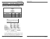
The RS-422 mode can be used for full duplex 4-wire RS-485 operation
provided that the serial server is acting as a sole master connecting to
all the slave devices, and all slave devices share the Receive signal
lines to the master. Set Flow Control for none, and omit connections to
RTS/CTS line pairs.
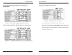
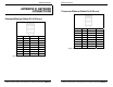
Serial Server pin-out
in RS-422 mode
RS-422
Device
RS-422 Signal Names DB-9
Pin#
Connections Signal
Receive A (-) RXDA(-) 1 TDA(-)
Receive B (+) RXDB(+) 2 TDB(+)
Transmit B (+) TXDB(+) 3 RDB(+)
Transmit A (-) TXDA(-) 4 RDA(-)
Ground GND 5 GND
Clear to Send A (-) CTSA(-) 6 RTSA(-)
Clear to Send B (+) CTSB(+) 7 RTSB(+)
Ready to Send B (+) RTSB(+) 8 CTSB(+)
Ready to Send A (-) RTSA(-) 9 CTSA(-)