
Server User Manual


Using ESP Manager
Manual Documentation Number: ESP901-902_4105m Chapter 4 23
B&B Electronics Mfg Co Inc – 707 Dayton Rd - PO Box 1040 - Ottawa IL 61350 - Ph 815-433-5100 - Fax 815-433-5104 – www.bb-elec.com
B&B Electronics Ltd – Westlink Commercial Pk – Oranmore, Galway, Ireland – Ph +353 91-792444 – Fax +353 91-792445 – www.bb-europe.com
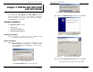
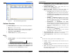
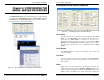
Figure 21. The VLINX ESP Manager Window
Software Overview
The VLINX ESP Manager window provides the following information:
•
Menus (Server, View, Exit, Help)
•
Server Icons (Firmware Upgrade, Virtual COM Configuration,
Searching Server, Uninstall Virtual COM, Monitor Port Status)
•
Serial Server / Virtual COM Lists
•
Software Status (Ready, Updating, Searching, etc)
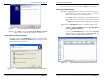
Menus
Server
• Firmware Upgrade - Used when downloading new firmware to
the Serial Server.
N
N
o
o
t
t
e
e
:
:
See Chapter 8 for more information on upgrading firmware.
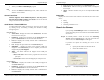
• Virtual COM Configuration - Selects the Virtual COM List.
Double clicking on any COM port in the
Virtual COM List brings
up a window that allows changing the virtual COM settings such
as
Flow Control, Protocol, IP address, and Port Number. Virtual
COM settings must match
Serial Server port settings.
Using ESP Manager
24 Chapter 4 Manual Documentation Number: ESP901-902_4105m
B&B Electronics Mfg Co Inc – 707 Dayton Rd - PO Box 1040 - Ottawa IL 61350 - Ph 815-433-5100 - Fax 815-433-5104 – www.bb-elec.com
B&B Electronics Ltd – Westlink Commercial Pk – Oranmore, Galway, Ireland – Ph +353 91-792444 – Fax +353 91-792445 – www.bb-europe.com
• Searching Server - Searches for Serial Servers on the network
and brings back configuration information that will be displayed in
the
Server Properties window.
•
Uninstall Virtual COM - Allows virtual COM ports to be
uninstalled from the ESP Manager window.
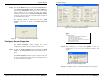
•
Monitor Port Status - Brings up a screen that displays the
following information associated with the selected serial port:
o Serial TX: Displays the number of bytes of data sent to
the
serial device since the IP connection was established.
o Serial RX: Displays the number of bytes of data received
from the connected
serial device since the IP connection
was established.
o DTR/RTS: The
DTR/RTS Port Status indicator displays
the current logic state of the DTR and RTS hardware
handshake (output) lines for the selected
Serial Server
port (1 = asserted, 0 = not asserted).
o DCD/DSR/CTS: The
DCD/DSR/CTS Port Status
indicator displays the current logic state being received on
the DCD, DSR and CTS hardware handshake (input) lines
for the selected
Serial Server port (1 = asserted, 0 = not
asserted)
o Status: Indicates whether the client software has made a
connection with the
Serial Server.
o IP Address: Displays the IP address of the connected
client when there is a client connection
•
Save Configuration File - Allows the user to save the current
configuration information to a file with a .vcom extension.
•
Load Configuration File - Allows the user to load a configuration
file.
View
Provides three viewing options for the ESP Manager screen:
•
Toolbar – allows the toolbar (directly under the menu bar) to be
viewable or hidden
•
Status Bar – allows the Status Bar (at the bottom of the screen to
be viewable or hidden
•
Split – allows the position of the split between the Icons pane and
the Virtual COM List / Serial Server List panes to be dragged
horizontally using the mouse