Competition Electronics, Inc Turbo35-GFX User’s Manual and Guide to Electric R/C Racing Competition Electronics, Inc 3469 Precision Dr.
TABLE OF CONTENTS INTRODUCTION TO THE T35-GFX: A TOOL TO MEASURE AND CONDITION YOUR CELLS 4 WARNING 4 HOW TO USE THIS MANUAL 5 QUICK START: A STARTING LINE VIEW OF THE T35-GFX 5 PREPPING THE T35-GFX FOR USE.......................................................................................................... 5 POWERING UP THE T35-GFX................................................................................................................. 6 GETTING FAMILIAR WITH THE T35-GFX MENU SYSTEM....
WHAT CAN I DO WITH MY T35-GFX? 22 THE MODE BUTTON........................................................................................................................23 THE PAGE BUTTON......................................................................................................................... 24 THE START/STOP BUTTON........................................................................................................... 24 THE ROTARY DIAL SWITCH AND THE CURSOR.............................
HOW TO CONTACT COMPETITION ELECTRONICS..................................................................................
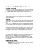
Introduction to the T35-GFX: A Tool to Measure and Condition your Cells Congratulations on your purchase of our Turbo35 GFX! The T35-GFX is a state-of-theart, competition-grade battery charger/discharger/motor run machine. If you are new to the T35-GFX it will take a while to become fully familiar with its many advanced features. However, the T35-GFX is designed so that its basic functions are easy to use, right out of the box. If you’ve used other CEI products, you’ll feel right at home with the T35-GFX.
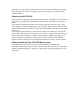
• • Specifications: This section contains a concise technical summary of the T35GFX capabilities and requirements data. When it doesn’t work: In this section you learn how to tell if your T35-GFX is broken, and what to do about it. Also, look here for information about how to get your T35-GFX upgraded, calibrated, etc. Quick Start: A Starting Line View of the T35-GFX This section of the manual will get you up and running fast.
Remember to put the alligator clip insulators on the wires before soldering the alligator clips, and make sure they’re far enough away from the solder joint so that they don’t overheat and melt. Powering up the T35-GFX The 14 gage 4 foot long pair of leads on the left side of the T35-GFX are to be connected to the DC power supply. The other leads are used to make connections to your pack or motor.
CHARGE MODE PAGE PAGE 1 PAGE 1ST PAGE SETUP MAIN SCREEN PAGE 2 2ND PAGE SETUP PAGE PAGE 3 TRICKLE DELAY START PAGE MODE DISCHARGE MODE PAGE PAGE 1 PAGE SETUP MAIN SCREEN PAGE MODE PAGE MODE CYCLE MODE PAGE 1 SETUP MAIN SCREEN PAGE MODE MOTOR RUN MODE PAGE PAGE 1 SETUP MAIN SCREEN PAGE MODE DATA MODE PAGE MAIN SCREEN PAGE 1 PAGE GRAPHS & READINGS PAGE 2 READINGS PAGE MODE PAGE SET MODE MAIN SCREEN PAGE 2 LOAD, SAVE AND NAME 10 SETUPS PAGE Figure 2. T35 GFX Menu Tree.
When you first turn on the T35GFX, the display will show the sign-on message, including the firmware revision number. This number corresponds to the version of software in the T35GFX. From time to time, CEI upgrades this software, either to fix firmware “bugs” or to add new features. The firmware revision number may be important if your Figure 3. Sign-on Screen. T35-GFX needs service; see “When it doesn’t work” for more details about this.
directions for adjusting the highlighted line, such as when you are creating names for setups, for example. Use of the buttons varies from the norm on some lines, and details are given for use when it is appropriate. So, you never really need the directions, once you’ve got a grasp of the basic use of each function. Just refer to the help line. Loading Factory Setups A lot of users have questions about how to set up their T35-GFX for different types of packs and motors.
discharge. That is why we have the additional small sense leads. These leads are designed specifically for measuring, and will have essentially no voltage drop at all, because the current flowing through these leads is relatively low. The advantage of this is that they can measure the voltage far more accurately. So in general, it’s best to always use the sense leads. However, the sense leads are not absolutely necessary for a charge cycle. Although the readings will be slightly off, it Figure 5.
5. Press “Start”. Quick Start: Motor Run 1. Navigate to the “mot mode” screen. There are no specific factory cycles for motor run, although values are saved and included in all setups. 2. Using the “Page” button, go to the “1 of 1” motor parameter screen and select the motor voltage and run time. 3. Connect Power and Sense leads to the motor. 4. Press “Start”. After you get up and running, be sure to read the rest of the manual.
extent, this is true. However, the goals of an R/C racer are different than the goals of an average user. In the case of the R/C racer, there is the need to balance cell longevity with performance. It is an inherent tradeoff racers make, so you should understand from the beginning that racers don’t treat their cells “nice”. As a result, they cannot be expected to last as long as they might in a less demanding application.
Single Cell Testing Figure 7. T35-GFX with Single Cell Holder. If you’re planning on doing a lot of single cell testing, you will want to get a cell holder from CEI, #CEI -2090. See our website for this and other products. To use the optional battery box, connect the large alligator clips to the bare 14 gauge wires on the battery box, (red to red and black to black) or install a high quality connector of choice.
The contacts used are tin-plated contacts. The contacts can be (and should be) cleaned using a model train track cleaner for brass tracks such as Rail Zip® made by Pacer Tech. To Recap… So, start with the appropriate factory preset. Talk to other racers. Do your research on the internet. Then, take an old pack and start to modify the settings, and keep track of the changes in a notebook. Log the charge settings and the results when you discharge.
to provide useful power. It will result in a higher number than Discharge Average Volts and represents the voltage over a more useful range. Run Time How long from the start of discharge until cutoff at the set discharge current? Longer is better, if you need the time. If your races are short, that means that the pack could have delivered more power if it was required.
It has been largely replaced by Actual Internal Resistance, another CEI innovation in R/C racing competition-grade equipment. Maximizing Performance: What helps, what doesn’t Understanding Cell Rating and Manufacturer’s Specifications If you buy your cells from a distributor or matcher, you may not have thought about the fact that they are a middle man to the manufacturer. Google for the manufacturer’s website; you may find valuable information concerning the cells you are using.
For smaller capacity cells, it’s probably a good idea to stick to 1C charge rates, but as the cell capacity gets larger, the cell can handle higher rates. For another, there is some evidence to indicate that a higher charge rate will result in better performance on the track. Racers routinely charge these cells at 5A (5000mA) and better.
When charging properly functioning NimH packs, during the first part of the charge process the cells will self heat slightly. NiCd cells do not exhibit this self-heating behavior before peaking. For both types of cells, temperature will rapidly rise as the pack nears full charge. Normally, for good cell longevity, it is desirable to minimize cell heating as much as possible.
reason for this is the fact that cell capacities have increased. Another reason is that R/C motors these days draw a lot of current, so it takes a higher discharge rate to emulate these high currents. The discharge function is the main tool that you use to compare cell performance. You can discharge a cell or a pack to a defined cutoff voltage at a fixed current and observe the discharge voltage over time as a graph, as well as time the discharge duration.
Another reason for matching cells is that over the course of multiple charge/discharge cycles, the state of charge of the individual cells within the pack becomes imbalanced. Matching is a way to restore and recharacterize (test ‘em again) each cell and even to gain information that will allow you to recombine these cells into new, different combinations when their characteristics change; to “rematch” them. The primary number for matching cells is the discharge time.
large currents from small capacity cells. You should not try to run these profiles on cells smaller than, say, 2000 mAHr rating, as it will attempt to draw 45 amps from the cells at times during the profile execution. Zapping: What is it and what does it do? “Zapping” is a process where special equipment is used to discharge a high voltage pulse through a cell. Each battery matcher will have their own way of doing this, and will not likely reveal the details of their process.
Sometimes, racers get in line like lemmings to chase after the latest gimmick. We find that these gimmicks peter out after a little while, as racers discover that they don’t do anything (useful, that is…). If you hear about some new technique, feature or device and you want to know if it works, use the T35-GFX to check it out. Then, instead of guessing, you’ll KNOW.
Figure 11 T35-GFX Front Panel Controls. They are: • • • START/STOP MODE PAGE The MODE Button The T35-GFX display can be advanced from one mode screen to the next by pressing the MODE button.
You can always tell what MODE you are in by observing the MODE STATUS display in the upper-right-hand corner of the display. They are: • • • • • • chg mode dcg mode cyc mode mot mode dat mode set mode Figure 12. Typical status screen Regardless of what PAGE you are on in a given showing the mode display in the MODE, pressing the MODE button will always upper right hand corner. advance the display to the main screen of the next mode.
and CYCLE modes will jump directly to the main MODE screen and start that MODE. Whenever the T35-GFX is executing a CHARGE, DISCHARGE, or CYCLE MODE, pressing the START/STOP button will stop the MODE execution. In the case of some parameters, the START/STOP switch will advance sequentially through a line of single characters, such as when you enter a new name for a setup. The Rotary Dial Switch and the Cursor Adjustable parameters appear as reverse highlighted lines on the SETUP screens.
The main display for the charge mode will show you the currently selected setup, the pack voltage, the charge rate, the mAHrs delivered to the battery, the elapsed seconds since the start of the charge cycle, the number of peaks set, the charge current setpoint, and the status of the Long Lockout and TurboFlex features. Charge Power Dissipation Limit The T35-GFX will limit the maximum power dissipated within the charge output power MOSFETs to 185 watts.
Peak Detect Voltage Peak Detect Voltage appears on the display as “Peak Det V”. This is the dropback voltage setpoint at which the T35-GFX will automatically terminate the charge operation. Units are in volts. Turn the ROTARY DIAL SWITCH to set the Peak Detect volts. TurboFlex On/Off TurboFlex On/Off appears on the display as “Turboflex”. This is the setting that turns the TurboFlex feature On and Off. Rotating the ROTARY DIAL SWITCH will toggle the setting.
Delay Delay appears on the “Peak 2” page of the charge mode screens. Use it to set the number of seconds between the first and second peak functions. One reason to use the delay is to let the pack rest after the first peak. Interpreting the Results Much of the data collected and calculated during the charge cycle is displayed on the pages of the data mode screens. Where that is the case, it will be indicated in the text below.
When you change the charge rate during a cycle, the 60 second lockout will be reactivated to assure that no false peaking results from the changed voltage across the pack due to a change in charge current. Viewing the Charge Graph While the charge cycle is in process, pressing the MENU button will toggle back and forth between the main charge screen and the realtime charge graph. More will be said about the graphing feature later in this document. Figure 14. Typical charge graph.
To navigate to the discharge screen, press the MODE button until “dcg mode” appears in the upper right hand corner of the display. Discharge Amps Discharge Amps can be found on page 1 of 2 of the setup screens for the discharge mode. It appears on the page as “Dcg Amps”. Adjust for the desired discharge rate. # of Cells Selecting the number of cells will automatically select the cutoff voltage. However, the value of the cutoff voltage may be customized, see “Cutoff Volts”, below.
Cutoff Voltage The discharge cycle is terminated when the pack voltage reaches the cutoff voltage setpoint for the discharge cycle. Changing the cutoff voltage setting will affect the cutoff voltage only for the number of cells selected. AIR ON/OFF This will turn the actual internal resistance measurement on or off.
A pack or cell powering a load can be approximated by a voltage source in series with a resistance, delivering power to a load, such as a motor. Ohm’s Law Voltage (volts) = Current (amps) x Resistance (ohms) tells us that current will decrease when resistance increases. Lower current means in turn a lower voltage delivered to the motor, which means less power delivered to the wheels. So, it follows that one important way to compare packs is to measure it’s actual internal resistance.
Cycle Mode Cycling is just a way of automating a charge cycle followed by a discharge cycle. You will always have to get charge into a pack before you can get anything out; therefore cycling is a useful feature. Cycling makes use of the charge and discharge features already discussed, and so most of the settings for a cycle are already complete from previous setup sessions already discussed.
Setting up the Motor Run Cycle To set up your motor run cycle, use the PAGE button to move to page “1 of 1” in the motor function mode. Here you will find two settings. Motor Volts Select the desired motor voltage here. Run Time Minutes Select the run time in minutes here.
Comm Setting Figure 16. T35-GFX serial port connector. The T35-GFX has a built in serial port on its side that can be used to transfer certain data out of the unit. The comm. setting is the setting that selects the format of data being sent out of the T35-GFX.
an ASCII printer. However, because the data is transmitted through a serial port, a device known as a Serial to Parallel converter is necessary in order to make a direct connection between the printer and the T35-GFX. Alternately, the ASCII graph may be captured using a PC, and then sent to the PC printer like any other document. These features are discussed in more detail later in this manual. COMP MAN and COMP AUTO COMP MAN and COMP AUTO are intended for PC interface for TurboLabel use.
on PC’s, some of our customers may not have a serial port on their computers. In this case, CEI recommends the purchase of a USB to Serial adapter device. These can be had for between $20.00 (internet) and $40.00 (your local “big-box” store). Here is the schematic for those who do not have a Radio Shack at their disposal. Figure 18 PC Serial Cable for use with T35-GFX.
What does the data look like as it comes out of a T35-GFX? Here’s a sample: 8.157, 5.743, 0 8.190, 6.051, 1 8.212, 6.036, 2 8.238, 6.002, 3 8.256, 6.007, 4 8.271, 6.012, 5 8.289, 6.012, 6 8.304, 6.012, 7 8.315, 6.017, 8 8.326, 6.017, 9 8.340, 6.021, 10 ……………….. The format for the data is often referred to as .csv or, comma separated value format. Helper programs from Microsoft® and others know how to read these types of files, and separate lines into individual values.
Figure 19. Serial to Parallel conversion gear. 1. On top of the converter are a series of small switches. Note that they are labeled: “1”-”8”. Also note the markings: “off”, and “on”. Using a pointed object such as a pencil, set the switches as follows: switch 1 2 3 4 5 6 7 8 setting ON ON OFF ON OFF OFF OFF OFF 2. Connect cables as shown in the picture above. Connect the free end of the smaller PC serial cable to your Turbo35’s RS-232 serial port.
Male DB9 to Male DB9 Gender Adapter #26-231 This Serial <-> Parallel converter is made by B&B Electronics Mfg. Co., Inc. The B&B part number is 232SPS2. More information about this device, including a user’s manual in .PDF can be found at their website, which is www.bb-elec.com. For European customers, you can use their European website, which is www.bb-europe.com. The Radio Shack and B&B trademarks are the exclusive property of these companies.
Data Collection and Storage Data points for the graphs are collected and stored in nonvolatile memory in the T35GFX during charge and discharge operations. Data storage is limited to the most recent 500 data points for the charge cycle and 500 data points for the discharge cycle. Data points are collected every 5 seconds, meaning that a maximum of 2500 seconds worth of data can be collected for each of the charge and discharge cycles.
Comm Mode Beeper State Charge # of Peaks Trickle Status On/Off Charge Cycle 1 Charge Amps Charge Cycle 1 TurboFlex Status On/Off Charge Cycle 1 Delay Seconds Charge Cycle 1 Peak Detect Volts Charge Cycle 1 Turboflex Level Charge Cycle 2 Charge Amps Charge Cycle 2 TurboFlex Status On/Off Charge Cycle 2 Delay Seconds Charge Cycle 2 Peak Detect Volts Charge Cycle 2 Turboflex Level Discharge Discharge Cycle Cell Count Discharge Cycle Cutoff Volts 1 Cell Discharge Cycle Cutoff Volts 2 Cell Discharge Cycle Cuto
Loading Setups Figure 21. Loading a setup. To load a setup, navigate to the Load line on page 1 of 1 of the set mode screen. When highlighted, rotate the dial. As you do, the setup number and name will change. When you se the setup you want to load, press START. This loads the selected setup into the T35-GFX active memory. Saving Setups To save the current setup, navigate to the Save line on page 1 of 1 of the set mode screen.
Naming/Renaming Setups Figure 22. Renaming a setup. A saved setup can be renamed in two steps. First, navigate to the Rename line on page 1 of 1 of the set mode screen. When the cursor is positioned on the Rename line, the first character position of the name will begin to flash. In this line, the START button functions differently. It advances the character position to the next character. To change the current character, rotate the rotary dial.
Machine This setting sets the machine name for computer data output. It allows external programs like TurboLabel to distinguish between different machines. TurboLabel Output The T35-GFX has a selection in the COMM DATA parameter line called COMPUTER DATA OUT. This is the setting meant to be used with TurboLabel. The T35-GFX packet format is compatible with older T35’s, even though the T35-GFX does not generate all the data that older T35’s do.
8 9 10 11 12 13 14 15 3.60 6 Turbo35 : Turbo35 : 1 174 23.9 20 16 17 18 19 1275 06.87 0120 0000 20 21 22 05.0 05.0 00.0 23 24 25 0.03 0.03 0.00 26 27 28 29 30 31 32 1555 013981 ON or OFF 3 ON or OFF 3 OFF 33 0 34 # 35 } (off road). Cutoff Volts for discharge. X.XX with leading zeros. Number of cells. One digit. Name 1. Always 9 chars. User editable. Name 2. Always 9 chars. Not user editable. Setup number; 1 digit. 0 through 9 represents 1 through 10.
You can obtain very good books on the Windows operating system at your local chain bookstore or computer store, or on the internet. Videos are also available. So there is no dearth of how-to information about PC usage. Take the time to learn your way around the computer. That would include being able to locate files on your PC, move them, delete them, rename them, copy them, etc. Become familiar with the computer operating system interface; it will pay big dividends down the road.
Capturing and Saving Data Ok. I said I wasn’t going to do this, but here is a brief, but detailed description of how to get around in Windows in order to capture files using HyperTerminal. Locate the menu selection at the top of the HyperTerminal program window that says “Transfer.” Use your mouse and left click one time on this menu item text. A drop down menu will appear; move the mouse pointer down by moving your mouse until the menu item “Capture Text” is selected and left click one time.
The name of the file is found at the far right side of the path text string; in this case the name of the file is “stringdata.txt.” You can control the file’s name and its contents by naming it at this point, in like manner. In general, perform this step first, each time you want to capture data from the T35-GFX, in order to control what data appears in the text file.
Below is a screen shot of what this program looks like. Again, things can vary greatly depending on how you have your Windows operating system configured, and which Windows operating system you are using. To cover these things is beyond the scope of this document; seek out a video or book on basic Windows Operating System Commands.
When you see the file displayed in the left-hand window, double left click on it; if you have named your file with a “.txt” extension, a built in program called Windows Notepad will automatically open up and display the contents of the file… Notice how your data has been captured in this file; Left click File, then Print Menu selections to print this data. In order to store other data, just repeat this process, using a different file name. Tera Term HyperTerminal, as mentioned previously, is a bit clunky.
For use with the T35-GFX, we’re interested in its ability to import data. In order to try this, you’ll have had to have previously captured real-time data from your T35-GFX in a file. If you haven’t done that yet, do it now; then return to this section. To import data into Excel, launch the Excel application, and using the File|Open menu selection, locate and open the captured file.
Notice that in the Open dialog box, ”Files of Type” shows a selection of .csv and .txt. You must do this. A series of dialog boxes called the “text import wizard” will appear to guide you through the import procedure. Be sure to select the “Delimited” for Original Data Type. Then click “Next”. In this window, make sure to select the “Comma” checkbox for the Delimiter type.
Then click “Finish”. Data will appear in your spreadsheet. Voltage is what were interested in here, so left-click the column header “A” with your mouse.
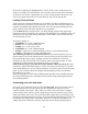
Now, click the graph icon on the top toolbar. This will activate the graphing wizard. A little time fiddling with this feature in Excel should yield a graph like this: Excel has many other graph formatting options you can experiment with. There is also the possibility of overlaying multiple graphs, and actually performing scientific analysis on the collected data.
Specifications Operating Temperature Range (non-condensing) Power Supply Input Range Charge Current Setpoint Range Charge Current Setpoint Resolution Max Charge Start Delay Discharge Current Setpoint Range Discharge Current Setpoint Resolution Motor Current Range Motor Voltage Setpoint Range Cooldown Delay Between Cycles Max Delay Between Peak Detects 1 and 2 Trickle Charge Rate Peak Detect Voltage Setpoint Range Auto Repeak Built-in Peak Detect Lockout Time Long Lockout Peak Detect Time (optional) Cell Cou
Some supplies have a feature called foldback current limiting. This form of current limiting reduces the voltage output current of the supply drastically when overloaded, but then locks the voltage at some low level until the load is removed. This is generally undesirable, but you can use foldback limited power supplies as long as you are aware of the issue and don’t exceed the power supply’s foldback current limit rating.
Fuses Figure 23. 20 amp fuses. Sooner or later, you’ll blow one or more fuses on your T35-GFX, so go to the local auto parts store and buy some extras now. The two forward located fuses protect the charge and discharge power circuitry. The rearmost fuse protects the power supply input circuit. All are rated at 20 A. If you blow one of the forward fuses, change both, because they are connected in parallel and it is most likely that if one blows, the other has been stressed and will blow shortly.
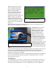
Voltage Drop, Resistance, and the Proper Use of Sense Leads Figure 24. A pack properly connected to the T35-GFX. When using the T35-GFX, during discharge, always be sure to connect the small sense leads directly to the pack solder connections. Don’t clip them to the larger power alligator clips. Don’t cut the clips off and solder them into the main connector. They need to have their own direct connection to the pack in order to get accurate readings.
a daytime phone number so that we can call you with the exact cost. You will need to obtain a cashiers check or money order in the correct amount. When you return your T35-GFX, include the following: • A return address • A daytime phone number • An explanation of the problem. For warranty repair, also include: • A copy of a dated receipt of purchase. Please see the warranty information, printed later on in this manual, for specific warranty details.
***Limited Warranty*** COMPETITION ELECTRONICS, INC., warrants the product manufactured by it to be free from defects in material and workmanship for a period of 90 days from date of purchase by the original purchaser for use. COMPETITION ELECTRONICS, at it’s option, will repair or replace without charge, or refund the purchase price of, any product which fails during the warranty period by reason of defect in material or workmanship found upon examination by COMPETITION ELECTRONICS, INC.