
Specifications

S7-200 Programmable Controller System Manual
398
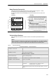
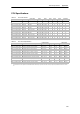
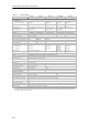
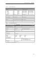
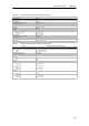
Table A-7 CPU Digital Output Specifications
General 24 VDC Output
(CPU 221, CP U 222,
CPU 224, CPU 226)
24 VDC Output
(CPU 224XP)
24 VDC Output
(CPU 224XPsi)
Relay Output
Type Solid State-MOSFET (Sourci ng) Solid State-MOSFET
(Sinking)
Dry contact
Rated voltage 24 VDC 24 VDC 24 VDC 24 VDC or 250 VAC
Voltage range 20.4 to 28.8 V DC 5to28.8VDC(Q0.0to
Q0.4)
20.4 to 28.8 VDC (Q0.5 to
Q1.1)
5 to 28.8 VDC 5to30VDCor5to250
VAC
Surge current (max.) 8 A for 100 ms 5Afor4s@10%duty
cycle
Logic 1 (min.) 20 VDC at maximum
current
L+ minus 0.4 V at max.
current
External Voltage Rail
minus 0.4V with 10K
pullup to External Voltage
Rail
--
Logic 0 (max.) 0.1 VDC with 10 K Ω Load 1M + 0.4V at max. load --
Rated current per poi nt (max.) 0.75 A 2.0 A
Rated current per c ommon (max.) 6A 3.75 A 7.5 A 10 A
Leakage current (max.) 10 µ A --
Lamp load (max.) 5W 30 W DC; 200 W AC
2, 3
Inductiv e clamp voltage L+ minus 48 VDC, 1 W diss ipation 1M+48VDC,1W
diss ipation
--
On S tate resistance (contact) 0.3 Ω ty pical (0.6 Ω max .) 0.2 Ω (max. when new)
Isolation
Optical (galvanic, field to logic)
Logic to contact
Resis tance (logic to contact)
Isolati on groups
500 VAC for 1 m inute
--
--
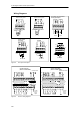
See wiring diagram
--
1500 VAC for 1 minute
100 M Ω
See wiring diagram
Delay (max.)
Offtoon(µs)
On to off (µs)
Switching
2µs (Q0.0, Q0.1),
15µs (all other)
10µs (Q0.0, Q0.1), 130µs
(all other)
--
0.5µs (Q0.0, Q0.1), 15µs (all other)
1.5µs (Q0.0, Q0.1), 130µs (all other)
--
--
--
10 ms
Pulse frequency (max.) 20 kHz
1
(Q0.0 and Q0.1) 100 kHz
1
(Q0.0 and Q0.1) 100 kHz
1
(Q0.0 and Q0.1) 1Hz
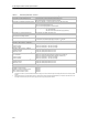
Lifetime mechanical cycles -- -- -- 10,000,000 (no load)
Lifetime contacts -- -- -- 100,000 (rated l oad)
Outputs on si m ultaneously All at 55° C (horizontal), All at 45° C(vertical)
Connecting two outputs in parallel Yes, only outputs in same group No
Cable length (max.)
Shielded
Unshielded
500 m
150 m
1
Depending on your pulse receiver and cable, an additional external load resistor (at least 10% of rated current) may improve pulse signal quality and noise
immunity.
2
Relay lifetime with a lamp load will be reduced by 75% unless steps are taken to reduce the turn-on surge below the surge current rating of the output.
3
Lamp load wattage rating is for rated voltage. Reduce the wattage rating proportionally for voltage being switched (for example 120 VAC -- 100 W).
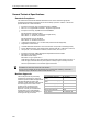
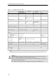
Warning
When a mechanical contact turns on output power to the S7-200 CPU, or any digital expansion module, it
sends a “1” signal to the digital outputs for approximately 50 microseconds.
This could cause unexpected machine or process operation which could result in death or serious injury to
personnel, and/or damage to equipment.
You must plan for this, especially if you are using devices which respond to short duration pulses.