
Specifications

Technical Specifications Appendix A
465
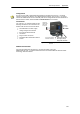
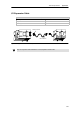
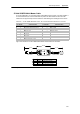
S7-200 RS -232/PPI Multi-Master Cable
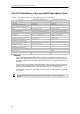
Table A-67 S7-200 RS-232/PPI Multi--Master Cable -- Pin-outs for RS-485 to RS-232 Local Mode Connector
RS-485 Connector Pin-out RS-232 Local Connector Pin-out
Pin Number Signal Description Pin Number Signal Description
1 No connect 1 Data Carrier Detect ( DCD) (not used)
2 24 V Return (RS-485 logic ground) 2 Receive Data (RD) (output from PC/PP I
cable)
3 Signal B (RxD/TxD+) 3 Transmit Data (TD) (input to PC/PP I
cable)
4 RTS (TTL level) 4 Data Terminal Ready (DTR)
1
5 No connect 5 Ground (RS-232 logic ground)
6 No connect 6 Data Set Ready (DSR)
1
7 24 V Suppl y 7 Request To Send (RTS) (not used)
8 Signal A (RxD/TxD--) 8 Clear To Send (CTS) (not used)
9 Protocol select 9 Ring Indicator (RI) (not used)
1
Pins 4 and 6 are c onnected internally.
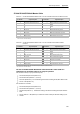
Table A-68 S7-200 RS-232/PPI Multi--Master Cable -- Pin-outs for RS-485 to RS-232 Remote Mode
Connector
RS-485 Connector Pin-out RS-232 Remote Connector Pin-o ut
1
Pin Number Signal Description Pin Number Signal Description
1 No connect 1 Data Carrier Detect ( DCD) (not used)
2 24 V Return (RS-485 logi c ground) 2 Receive Data (RD) (input to PC/PPI
cable)
3 Signal B (RxD/TxD+) 3 Transmit Data (TD) (output from PC/PPI
cable)
4 RTS (TTL level) 4 Data Terminal Ready (DTR)
2
5 No connect 5 Ground (RS-232 logic ground)
6 No connect 6 Data Set Ready (DSR)
2
7 24 V Supply 7 Request To Send (RTS)
(output from PC/PPI cable)
8 Signal A (RxD/TxD--) 8 Clear To Send (CTS) (not used)
9 Protocol select 9 Ring Indicator (RI) (not used)
1
A conversion from female to male, and a c onversion from 9-pin to 25-pin is required for modems.
2
Pins 4 and 6 are c onnected internally.
Use the S7-200 RS-232/PPI Multi-Master Cable with STEP 7--Micro/WIN as a
replacement for the PC/PPI cable or for Freeport operation
For connection directly to your personal computer:
- Set the PPI/Freeport mode (Switch 5=0)
- Set the baud rate (Switches 1, 2, and 3)
- Set Local (Switc h 6=0). The Local setting is the same as setting the PC/PPI cable to DCE.
- Set the 11 Bit (Switch 7=0)
For connection to a modem:
- Set the PPI/Freeport mode (Switch 5=0)
- Set the baud rate (Switches 1, 2, and 3)
- Set Remote (Switch 6=1). The Remote setting is the same as setting the PC/PPI cable to
DTE.
- Set the 10 Bit or 11 Bit (Switch 7) to match the number of bits per character setting of your
modem.